AMF 90XLi PINSPOTTER
400-088-011 Page 2-6 Rev. 10/04
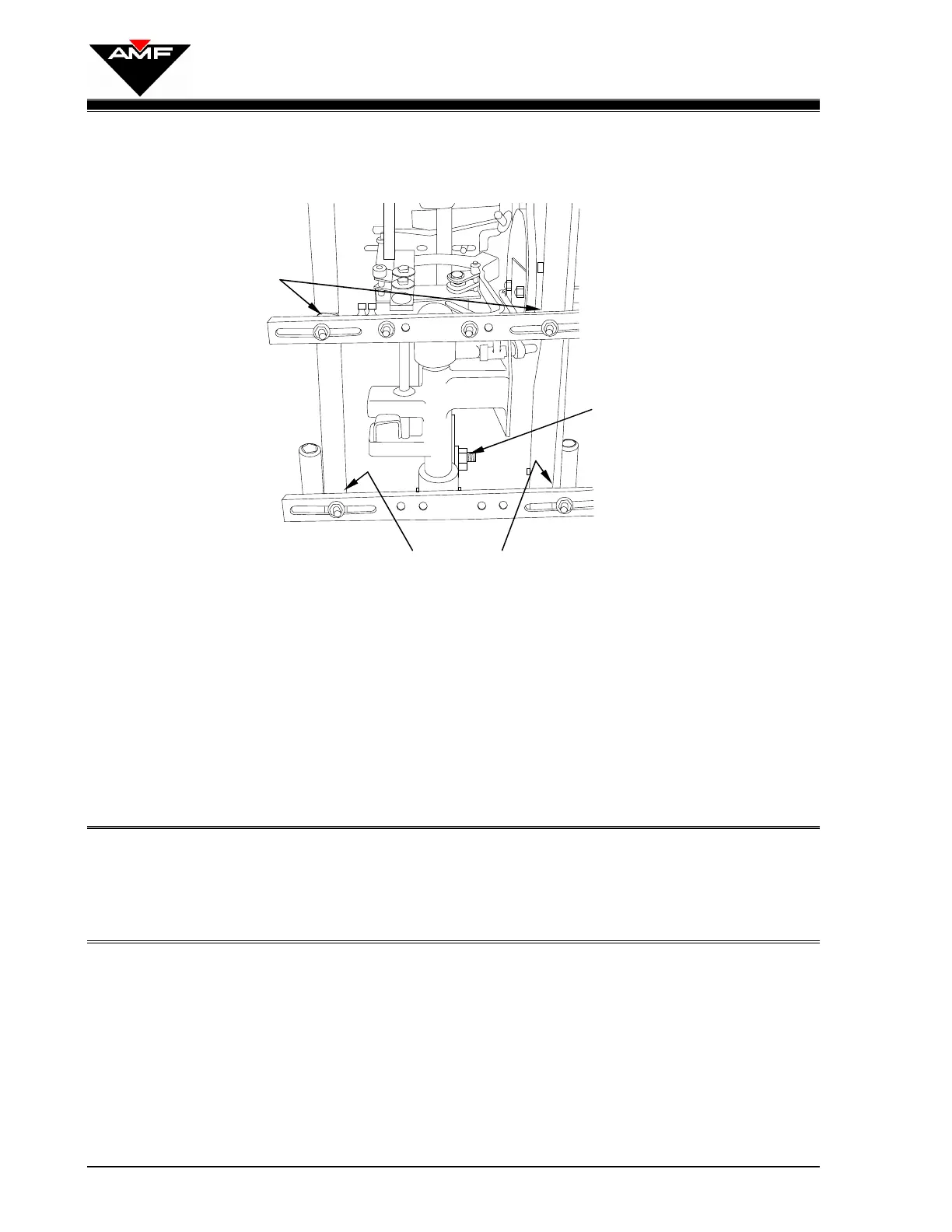
Figure 2-7
6. If not done previously, disconnect the spring from the belt tensioner and remove the
belt from the rudder drive pulley.
7. Reattach the rod assembly to the crank pin and pivot the sensor assembly by
manually rotating the rudder drive pulley to observe the travel of the rudder arm.
8. Adjust the length of the rod assembly so that the rudder arm swings equally to the
left and right of the center position. Tighten the rod’s jam nuts.
NOTE: Lengthening the rod provides more travel towards the odd machine while
shortening the rod provides more travel towards the even machine. The
rod assembly has right-hand threads on both ends, so the rod end must
be removed from the crank pin to make adjustments.
9. Loosen the pivot crank nut on the crank plate and rotate the plate in a
counterclockwise manner to increase the overall stroke of the rudder arm. The
correct adjustment is achieved when the rudder arm touches each rubber bumper
on the left and right side plates with equal force without actuating the trip cam
follower when the drive pulley is rotated. There should be a little overtravel (1/8
inch) on each side. Tighten the pivot crank nut.
10. Rotate the rudder drive pulley to recheck travel. If the rudder hits one bumper and
not the other, repeat Steps 8 & 9.
Shim Here to
Lower Rudder Arm
SENSOR - BACK VIEW
Shim Here to Raise
Rudder Arm
Rudder Arm Length
Adjustment Bolt