SECTION 2.0
Operation & Adjustment
400-088-011 Page 2-5 Rev. Date 10/04
2.7 Rudder and Sensor Adjustment
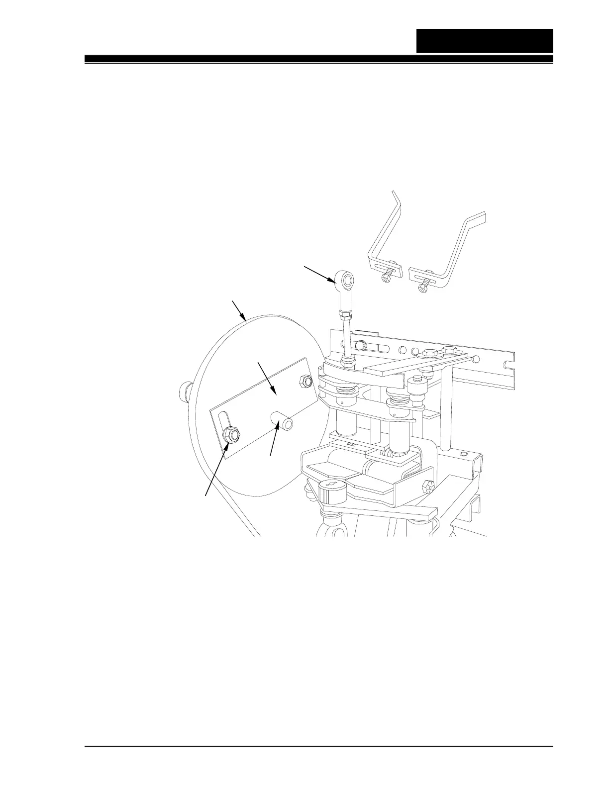
1. Remove the retaining nut from the crank pin and save (see Figure 2-6).
2. Remove the rod assembly from the crank pin and swing it out of the way so that the
sensor assembly can be moved manually.
Figure 2-6
3. Remove both reset cams.
4. Loosen the pivot crank nut and turn the adjusting plate to the full clockwise position,
then tighten the pivot crank nut to prevent the adjusting plate from moving.
5. Move the rudder arm back and forth, so that it touches the rubber bumper on each
side plate. The arm should move freely with no interference. If the paddle is not
centered in the door opening, it may be necessary to adjust the length of the rudder
arm for front-to-back alignment and/or shim the rudder arm support bracket for
vertical alignment as shown in Figure 2-7.
SENSOR - ADJUSTMENTS
Pivot Crank Nut
Crank Pin
Rod
Assembly
Reset Cams
Adjusting Plate
Sensor
Assembly
Rudder Drive Pulley