Amtech
A.12
13
A
Appendix-C: Trouble Shooting Guidelines
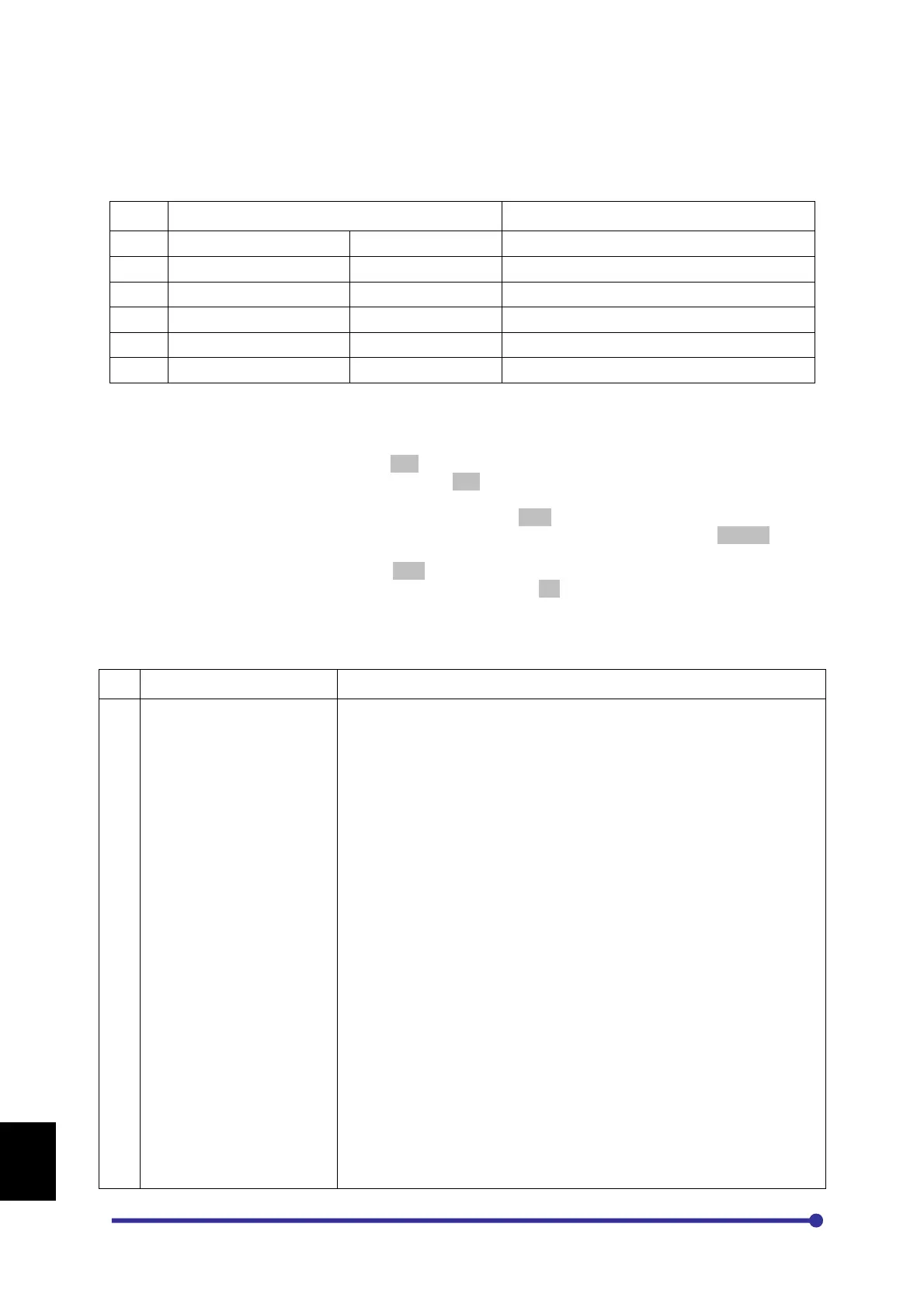
In case of fault condition, first ensure that the mains voltage applied at L1, L2 and L3 are ok.
Then check the control supply voltage in PCA-2014A.
Sr. No.
Measure @ Expected Voltage
If the above voltages are correct, check the following jumper positions.
Jumper Position
1. The equipment is shipped with JP2 in 10V position. When connecting potentiometer at FSV or
using 0-10V signals, ensure that JP2 is put in the 10V position.
2. The equipment is shipped with sink logic (JP1 is kept on Sink position) for the programmable
sequence inputs. To change the sink logic to source, change the jumper JP1 position to Source.
3. The equipment is shipped with JP3 in NLD position. This means the terminating resistors are not in
picture. To insert the terminating resistors, keep the jumper to LD position.
If the above jumper positions are correct, check the following as per the fault displayed on the
Operation Panel (LCD Display)
No.
Fault Name Causes & Countermeasures
1
If fault comes during stop condition,
1. The power module(s) in the main circuit may be damaged.
Switch off the power supply and check the power module(s).
2. There may be loose connection or improper connection of current
sensor cable or shorting in the cable.
Switch off the power supply and remove the cable. Check again. If
no fault is observed, there can be a problem in cable or connection.
Check the cable on both the sides for proper crimping. Insert the
cable properly and check again. If still problem persist, replace the
cable.
3. Current sensor may have failed.
Switch off the power supply and remove current sensor. Check
again. If no fault is observed identify the damaged current sensor
and replace it.
4. The fault may be from Driver Board side.
Switch off the power supply and remove the FRC in case of wire
interface. Check the cable on both the sides for proper crimping.
Insert the cable properly and check again. If the fault persists,
proceed for the next step.
In case of fiber optic interface, remove all the fiber optic cables,
check them and insert them again properly. Check again. If the
fault persists, proceed for the next test.
5. IGBT Gate Driver board may have problem.
Replace the IGBT Gate Driver board and check again. Take anti-
static precautions while changing the board.
If fault occurs during acceleration when the motor is connected,