EasyManua.ls Logo

Analog Devices EVAL-ADuCM355QSPZ User Manual

Analog Devices EVAL-ADuCM355QSPZ
24 pages
To Next Page IconTo Next Page
To Previous Page IconTo Previous Page
Page #10 background imageLoading...
Page #10 background image
UG-1308 EVAL-ADuCM355QSPZ Evaluation Board
Rev. A | Page 10 of 24
Compiling and Running Firmware
To compile and run the ADuCM355 firmware, take the
following steps:
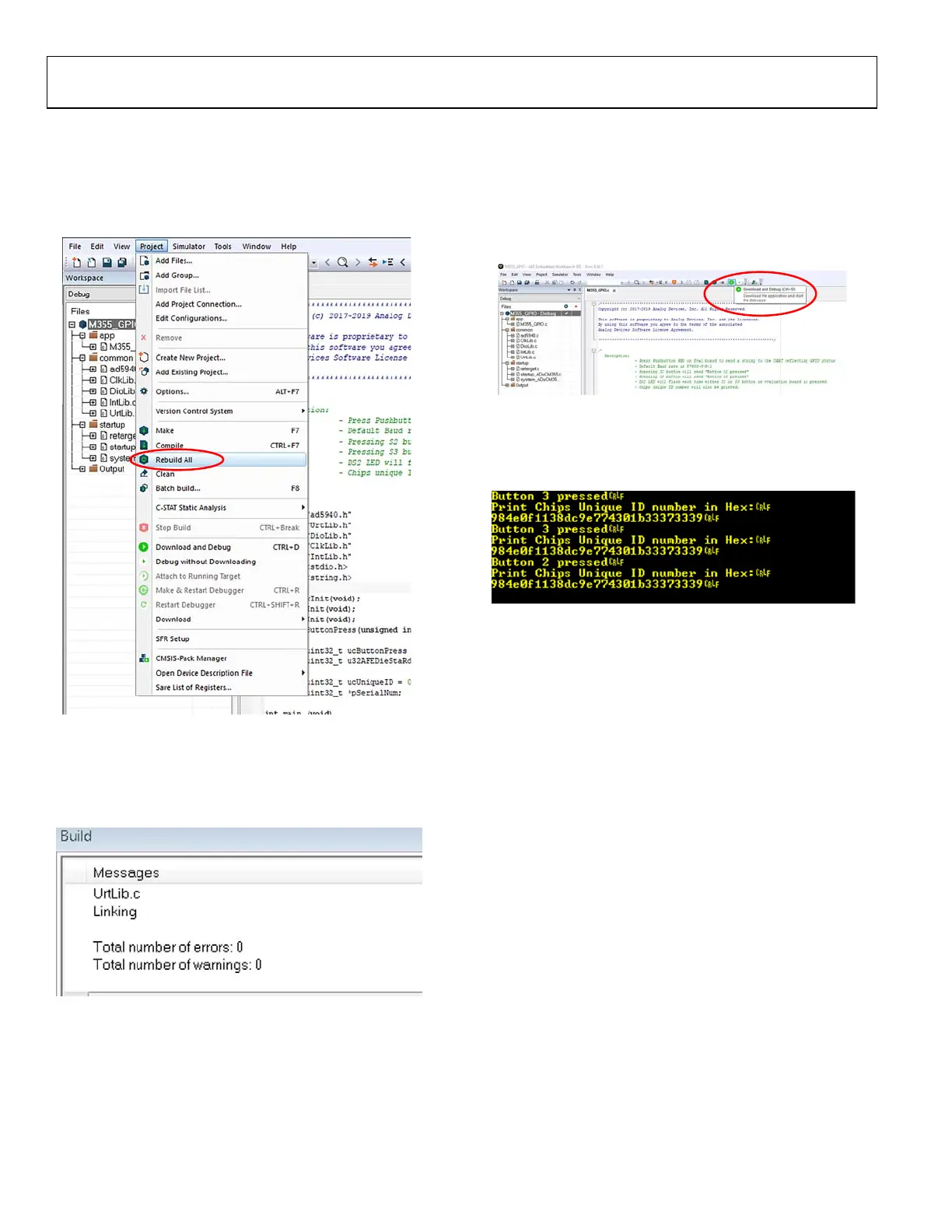
1. In the IAR Embedded Workbench window, navigate to
Project > Rebuild All (see Figure 10).
16887-010
Figure 10. Project > Rebuild All
2. Click Rebuild All. The IDE begins building the executable
from the source files, which may take a couple of seconds.
The message shown in Figure 11 appears in the Build window
when the build is complete.
16887-013
Figure 11. Build Output Window
3. To run the firmware on the ADuCM355, ensure that the
EVAL-ADuCM355QSPZ is powered on and the J-Link
debugger is connected to P3 on the EVAL-ADuCM355QSPZ,
then click Download and Debug to load the firmware to
the ADuCM355 and launch the debugger (see Figure 12).
Launching and downloading the debugger can take a few
seconds or more.
16887-011
Figure 12. Launching the Debugger
4. Open a terminal program such as RealTerm to view the
UART data from the ADuCM355 (see Figure 13). The
baud rate is 230,400 bps.
16887-113
Figure 13. UART Data in RealTerm
5. Figure 14 shows the debug interface. Click the blue arrow
(shown in the red circle) to begin code execution. The UART
prompts the user to press either the S2 or S3 button. The
DS2 LED toggles on and off with each button press.

Table of Contents

Question and Answer IconNeed help?

Do you have a question about the Analog Devices EVAL-ADuCM355QSPZ and is the answer not in the manual?

Analog Devices EVAL-ADuCM355QSPZ Specifications

General IconGeneral
CategoryEvaluation Board
Part NumberEVAL-ADuCM355QSPZ
MicrocontrollerADuCM355
EmbeddedYes
Operating Temperature Range-40°C to +85°C
Compatible DevicesADuCM355
ManufacturerAnalog Devices Inc.
FunctionEvaluation Board
PurposeEvaluation of the ADuCM355
InterfaceUSB, UART

Summary

EVALUATION BOARD FEATURES

ADuCM355 Debug and Programming

Debug and programming capabilities of the ADuCM355 microcontroller.

Electrochemical Sensor Evaluation

Evaluate performance with electrochemical gas sensors.

Temperature Sensor (ADT7420)

±0.25°C accurate temperature sensor via I²C.

MicroUSB Power and PC Connection

MicroUSB power option and PC connection for the evaluation board.

EQUIPMENT NEEDED

PC Requirements

PC running Windows® 7 or later.

Sensor Connection

Connect an electrochemical gas sensor or resistor star network.

DOCUMENTS NEEDED

ADuCM355 Hardware Reference Manual

Official hardware reference manual for the ADuCM355.

ADuCM355 Data Sheet

Comprehensive data sheet for the ADuCM355 microcontroller.

SOFTWARE NEEDED

Development IDEs

IAR Embedded Workbench or Keil µVision IDEs.

ADuCM355 GitHub Repository

Access firmware examples and code from GitHub.

Terminal Program

Terminal program such as RealTerm for viewing output.

GENERAL DESCRIPTION

ADuCM355 System Overview

ADuCM355 system for biasing and measuring electrochemical sensors.

Evaluation Board Purpose

EVAL-ADuCM355QSPZ allows evaluation of ADuCM355 performance.

Consult ADuCM355 Data Sheet

Consult ADuCM355 data sheet in conjunction with user guide.

POWER CONFIGURATIONS

MicroUSB Direct Power

Powering the board via the microUSB connector and on-board LDO.

3.3V Power via AVDD/DVDD

Connecting 3.3 V to AVDD and DVDD connectors for current measurement.

POWER VIA USB FROM 8-PIN DEBUG CONNECTOR (P27)

Jumper Setup for Debug Header USB Power

Jumper settings for powering via the 8-pin debug connector USB.

POWER VIA EXTERNAL 5V SUPPLY TO 2-PIN CONNECTOR (P37)

External 5V Power Setup

Connecting an external 5 V supply to the P37 connector.

CONNECTING AN ELECTROCHEMICAL SENSOR

Sensor Channels (CHO and CH1)

ADuCM355 has two measurement channels for electrochemical sensors.

Sensor Connection Types

2-lead, 3-lead, or 4-lead sensors can be connected to CH0 or CH1.

GETTING STARTED WITH THE TOOL CHAIN

Downloading Development Environment (IDE)

Download and install IAR Embedded Workbench or Keil µVision.

Installing ADuCM355 Support Package

Clone the ADuCM355 examples repository from GitHub.

RUNNING A GPIO EXAMPLE IN IAR EMBEDDED WORKBENCH

Project Folder Structure (IAR)

Structure of the IAR Embedded Workbench project folder.

COMPILING AND RUNNING FIRMWARE

Rebuild All Project

Compile the firmware by rebuilding all project files in the IDE.

Launching the Debugger

Load the compiled firmware onto the ADuCM355 and launch the debugger.

Viewing UART Data

Open a terminal program to view UART data from the ADuCM355.

RUNNING A GPIO EXAMPLE IN KEIL µVISION

Installing ADuCM355 Keil Pack

Download and install the ADuCM355 device family pack for Keil µVision.

Opening Pack Installer

Open the Keil pack installer to access device and example projects.

RUNNING A GPIO EXAMPLE IN KEIL µVISION (continued)

Copying and Building GPIO Project

Copy the M355_GPIO example project and build it in Keil µVision.

Loading GPIO Project onto ADuCM355

Load the GPIO example project onto the ADuCM355 using the mIDAS-Link debugger.

APPLICATION EXAMPLES

ADuCM355 SDK Overview

Overview of ADuCM355 SDK, including Cortex-M3 and AFE die.

Main Library Files (AD5940.c/h)

Main library files AD5940.c and AD5940.h for firmware development.

Example Projects List

List of example projects including Cyclic Voltammetry, EIS, etc.

CYCLIC VOLTAMMETRY EXAMPLE

Cyclic Voltammetry Measurement

Measure current response to ramp voltage on reference electrode.

AD5940RampStructInit Function

Modifying parameters for ramp voltage, peak voltage, and duration.

Test Cell Setup

Construct a dummy electrochemical cell using 1 kΩ resistors.

EIS EXAMPLE

EIS Measurement Process

Three-step process to measure response current to AC excitation.

Impedance Calculation Equation

Equation to calculate actual impedance using measured values.

EIS Parameters Configuration

Configuring parameters like LpTiaRf, LpTiaRl, and SensorBias in AD5940Main.c.

Running the EIS Measurement

Steps to launch debugger, open terminal, and start impedance test.

CHRONOAMPEROMETRY EXAMPLE

Chronoamperometry Measurement

Measure response current when voltage is stepped on electrochemical cell.

CHRONOAMPEROMETRY EXAMPLE (continued)

M355_ECSns_CapaTest Project

Project implementing chronoamperometric measurement.

AD5940AMPStructInit Function

Modifying measurement parameters for chronoamperometry.

Data Output Format

Results sent to UART including current, voltage measurements.

DC CURRENT EXAMPLE

DC Current Measurement

Measuring current output on the sense electrode with applied bias voltage.

M355_ECSns_SingleWE Project

Project implementing DC current measurement on a single electrode.

Test Setup and Configuration

Connecting 1 kΩ resistor, setting Vzero and SensorBias parameters.

4-LEAD ELECTROCHEMICAL SENSOR EXAMPLE

ADuCM355 Support for 4-Lead Sensors

ADuCM355 supports biasing and measuring 4-lead sensors.

M355_ECSns_DualWE Project

Project configures CH0 for bias and measures current via TIA0/TIA1.

Dual Working Electrode Configuration

Configuring parameters for dual working electrode measurement.

CONNECTING AN EXTERNAL GAIN RESISTOR ACROSS THE HIGH SPEED TIA

High Speed TIA Gain Resistor Options

Programmable gain resistor for high speed current measurement.

External Gain Resistor Connection

Connecting external RTIA resistor across AINO and DE0 pins.

M355_ExternalRTIA Example Project

Example project for setting up high speed TIA with external gain resistor.

AFE DIE WATCHDOG TIMER EXAMPLE

ADuCM355 AFE Watchdog Timer

Watchdog timer on AFE die, independent of Cortex-M3 core.

Windowed Watchdog Mode

Configuring the windowed watchdog mode using M355_AfeWdt project.

Watchdog Refresh Trigger

Watchdog refresh triggered by ASCII Character 1 from PC.

ADuCM355 SYSTEM CALIBRATION

Calibration Routines Importance

Calibration routines ensure high level of measurement accuracy.

HIGH SPEED TIA GAIN RESISTOR CALIBRATION

Gain Resistor Options

Three programmable gain resistor options for the high speed TIA.

Calibration Process Overview

Using high speed DAC and RCAL resistor for calibration.

Determining RTIA Resistor Value

Determining exact RTIA resistor value using known calibration current.

LOW POWER TIA0/TIA1 GAIN RESISTOR CALIBRATION

Low Power TIA Gain Resistors

Independent programmable gain resistor for low power TIA channels.

Calibration Current Generation

Using low power DAC to create calibration current across RCAL resistor.

LPTIA Gain Calibration Example

Project implementing function to calibrate gain resistor for LPTIA.

MASS ERASING A DEVICE NOT RESPONDING TO SWD COMMANDS

Recovering Locked Devices

Recovering devices locked during debug sessions or resets.

Mass Erase Procedure

Steps to mass erase user flash using S3 button and IAR IDE.

ORDERING INFORMATION

BILL OF MATERIALS

Related product manuals