EVAL-ADuCM355QSPZ Evaluation Board UG-1308
Rev. A | Page 17 of 24
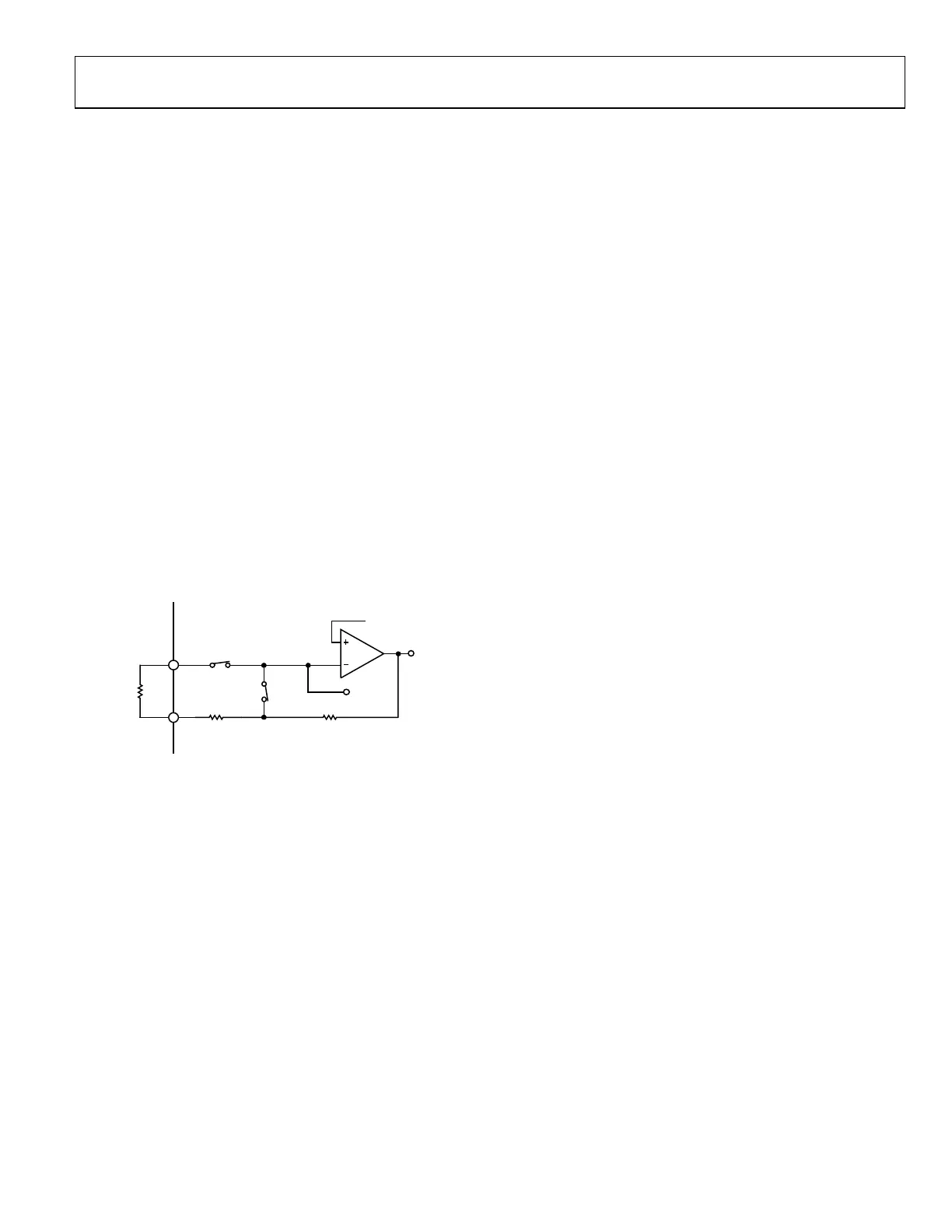
CONNECTING AN EXTERNAL GAIN RESISTOR
ACROSS THE HIGH SPEED TIA
The internal high speed TIA has a programmable gain resistor
that allows the user to either configure a high speed current
measurement channel for different input current ranges, or to
connect an external gain resistor instead.
The EVAL-ADuCM355QSPZ supports the connection of an
external transimpedance amplifier resistor (R
TIA
) across the
AIN0 pin and DE0 pin, which is labeled RTIA on the top side
of the printed circuit board (PCB).
The current flows from the AIN0 pin into the high speed TIA
inverting input with the HSTIA connected to the DE0 pin.
The ADC selects the HPTIA_P and HPTIA_N input channels to
measure the voltage drop across the external R
TIA
resistor (see
Figure 32).
When the user populates the external gain resistor, the gain
resistor can be used instead of the internal gain resistor. Figure 32
shows the external resistor connected to AIN0 and DE0. Note
that R
LOAD_03
and R
TIA2_03
are set to 0 Ω so as not to effect the
measurement.
The M355_ExternalRTIA code example project in the examples
folder demonstrates how to set up the high speed TIA for an
external gain resistor.
AIN0
T1
T10
HPTIA_N
HSTIA
EXTERNAL
R
CAL
DE0
R
TIA2_03
R
LOAD_03
1.11V REFERENCE
HPTIA_P
16887-030
Figure 32. ADuCM355 External R
TIA
Connection to the High Speed TIA
AFE DIE WATCHDOG TIMER EXAMPLE
The ADuCM355 supports a watchdog timer on the AFE die.
The watchdog timer clocks via an oscillator that is completely
independent of the clocks in the Cortex-M3 core. Therefore,
the watchdog timer meets the IEC 61508 requirement of an
independent watchdog timer for a microcontroller and eliminates
the need for an external watchdog timer chip.
The M355_AfeWdt code example project in the examples
folder shows how to configure the windowed watchdog mode.
The WDT_INTERRUPT_EN #define parameter configures the
project to generate either a reset or an interrupt.
The project uses a default timeout period of 16 sec. A minimum
waiting period of 4 sec is required before a watchdog refresh is
allowed. Refreshing the watchdog within 4 sec causes a reset or
interrupt to occur depending on the setting of Bit 1 of the
WDTCON register. If the timeout period elapses, a reset or
interrupt also occurs. To avoid a reset or interrupt generation,
refresh the watchdog timer within the minimum period of 4 sec
and the timeout period of 16 sec.
The watchdog timer refresh is triggered when the ASCII
Character 1 is sent from the PC.

 Loading...


