EVAL-ADuCM355QSPZ Evaluation Board UG-1308
Rev. A | Page 15 of 24
V
L
AGE
TIME
EXCITATION W
EFORM
16887-020
Fig
ure 26. Typical Chronoamperometric Voltage Stimulus Waveform
CURRENT
TIME
RESPONSE
EFORM
16887-120
Figure
27. Typical Chronoamperometric Current Response Waveform
In the ADuCM355 firmware development package, the M355_
ECSns_CapaTest project implements a chronoamperometric
measurement.
The AD5940Main.c file contains an
AD5940AMPStructInit()function that modifies the main
measurement parameters.
For the following example, only CH0 is used and all default
values are used. The resistor star model is connected to P5, as
per the examples described in the Cyclic Voltammetry Example
section and the EIS Example section.
Load the project in the preferred IDE and open a terminal
program. Compile and build the project and load the code onto
the ADuCM355. Start the code execution and save the UART
data to a .csv file for processing.
The example code sends the following three arrays of results to
the UART at a 230,400 bps baud rate:
The first set of values includes th
e current
measurement r
esults for the SE0 channel in μA
.
The next s
et of values includes the volt
age
measurement r
esults for the SE0 channel in V.
The final set of values includes the volt
age
measurement results for the RE0 channel in V.
–100
100
0
200
300
500
400
600
1
115
229
343
457
571
685
799
913
1027
1141
1255
1369
1483
1597
1711
CURRENT (µA)
INDEX
16887-122
Fi
gure 28. Output Data Using the M355_ECSns_Capatest Example with
Three 1 kΩ Resistors
DC CURRENT EXAMPLE
The dc current is a standard electrochemical measurement.
Depending on the sensor type, a bias voltage is applied between
the reference and sense electrodes. The current output on the
sense electrode is measured.
In the ADuCM355 firmware package, the M355_ECSns_
SingleWE project implements a dc current measurement on
an electrochemical cell connected to CH0. The measurement
parameters can be configured in the AD5940AMPStructInit()
function in the AD5940Main.c file. For testing purposes, connect
the 1 kΩ resistor star network to P5. Set the Vzero firmware
parameter to 1100 mV, and set the SensorBias firmware
parameter to 500 mV to apply a 500 mV bias across the 1 kΩ
resistor network. Ensure that the EVAL-ADuCM355QSPZ is
powered on and that the debugger is connected to the PC. Then
open the project in the preferred IDE, and compile and run the
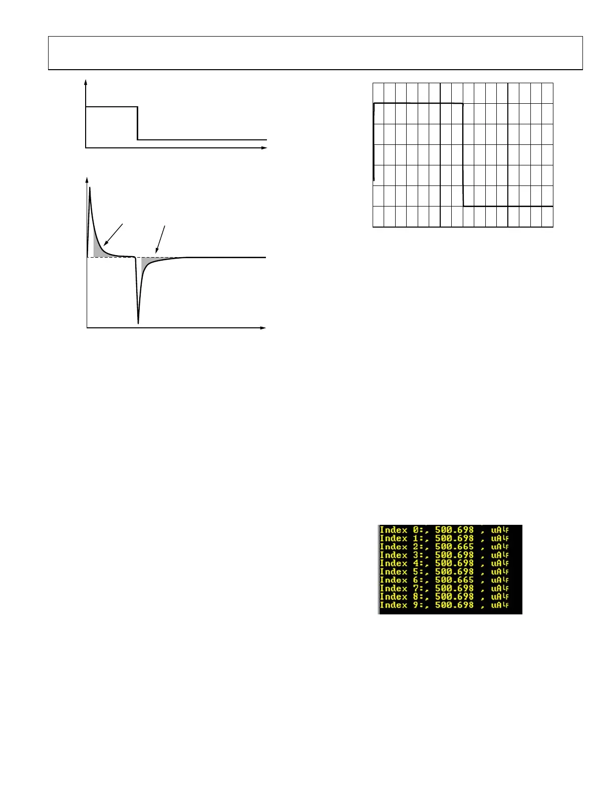
example application. Open a terminal program to view the
results. The output is the current measured through the SE0 pin
on P5 of the EVAL-ADuCM355QSPZ (see Figure 29).
16887-021
Fi
gure 29. CH0 Output

 Loading...


