UG-1308 EVAL-ADuCM355QSPZ Evaluation Board
Rev. A | Page 6 of 24
DIRECT 3.3 V POWER VIA THE AVDD AND DVDD
CONNECTORS
To measure the ADuCM355 current consumption (I
DD
), connect
3.3 V directly to the AVDD and DVDD connectors.
To power the EVAL-ADuCM355QSPZ in this case, apply a
3.3 V supply directly to Pin 1 on the AVDD connector and to
Pin 1 on the DVDD connector.
Jumper Setup with Direct 3.3 V Connection
The jumper settings required when using a 3.3 V connection
are as follows:
1. Insert JP32, JP34, JP43, and JP44.
2. Remove JP42.
For additional information, see Figure 6.
POWER VIA USB FROM 8-PIN DEBUG
CONNECTOR (P27)
If using the older USB-SWD/UART and debug interface, the
ADuCM355 can also be powered from the USB. The UART to
USB interface is handled by the USB-SWD/UART-EMUZ board.
Jumper Setup with Power via USB
Close JP35, JP40, JP42, JP43, and JP44 when using power via
the USB (see Figure 5).
16887-006
Figure 5. Power via 8-Pin P27 Debug Connector
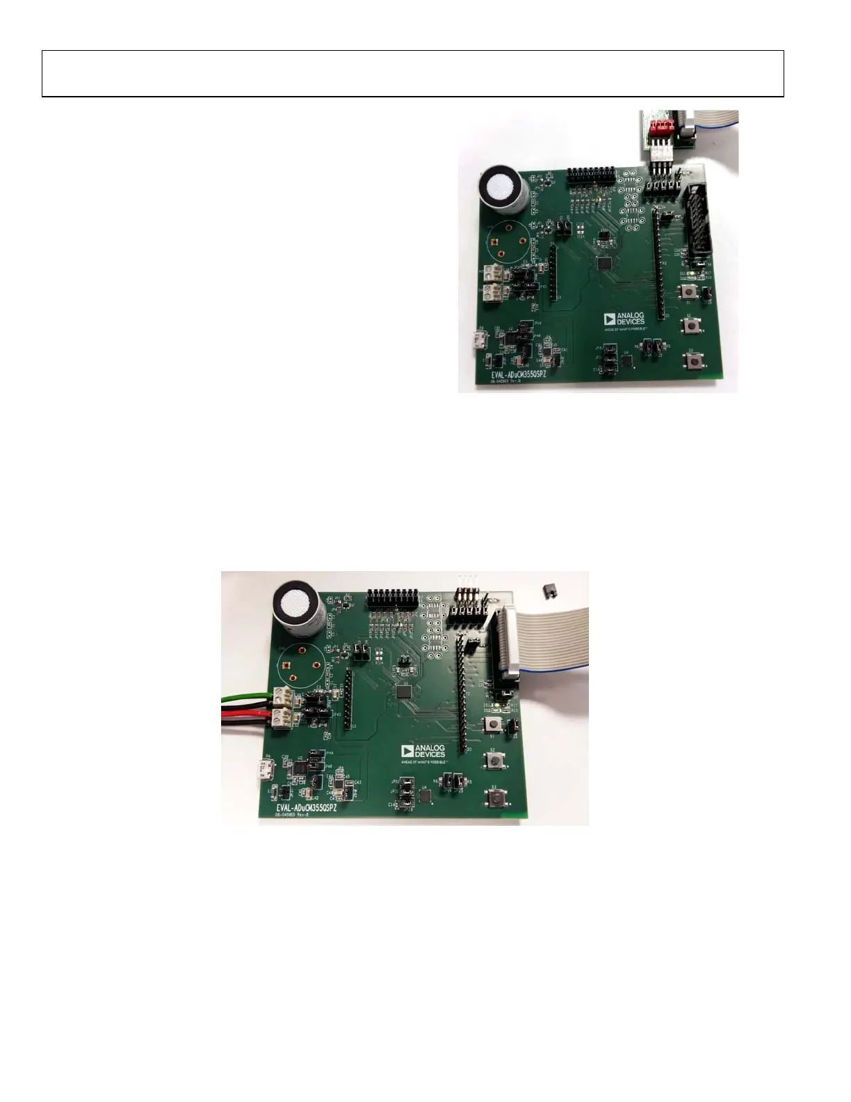
POWER VIA EXTERNAL 5 V SUPPLY TO 2-PIN
CONNECTOR (P37)
The last power supply option is to connect an external 5 V
supply to the 2-pin P37 connector. This 5 V supply is the input to
the ADP7158 LDO regulator that has a 3.3 V output voltage. Do
not connect the microUSB cable to P4. This option is a debug or
test option only.
16887-005
Figure 6. Power DVDD and AVDD Directly via Power Header Blocks

 Loading...


