20
ION-B User Manual
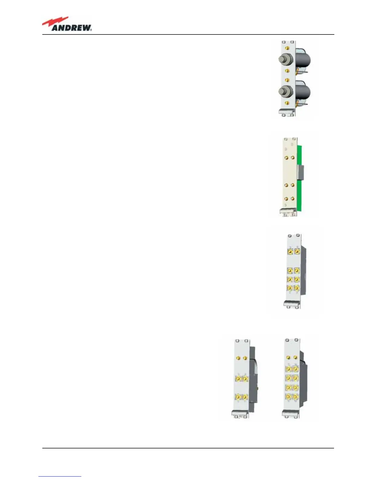
The variable RF attenuators (TBSI): they provide independent
attenuations (adjustable from 0 to 30dB, with 1dB steps) on uplink and
downlink RF paths, and allow the designer to optimize the signal level
close to the BTSs. TBSI is an override attenuator, its dimensions are: Width =
7TE, Height = 4HE.
The Dual Band Coupler (TLDN): in downlink, it combines a low band RF
signal (800 to 1000 MHz) and a high band RF signal (1700 to 2500 MHz) into
a common RF port; in uplink, it splits a composite signal between a low
band RF port and a high band RF port. Module dimensions are: Width = 7
TE, Height = 4 HE.
The Tri Band Coupler (TLTN): in downlink, it combines a Low Band signal, a
Middle Band signal, and a High Band signal into a communal one; in uplink,
it splits the triple band signal among the three RF single band paths.
Please refer to table 4.7.1 or to the bulletin PA-100596-EN for further
information about the different band confi gurations.
Module dimensions are: Width = 7 TE, Height = 4 HE.
The RF splitters/combiners (TLCN2 and TLCN4): TLCN2
is a 2-way splitter/combiner. TLCN4 is a 4-way splitter/
combiner. They can be used in a variety of different
situations, such as:
• To connect a BTS with several master optical TRXs.
In uplink, the TLCN2 (or TLCN4) combines 2 (or 4) RF
signals which come from different master optical
TRXs into a common RF signal entering the BTS. In
downlink, the TLCN2 (or TLCN4) splits the downlink
composite RF signal which comes from the BTS into 2
(or 4) RF ports, entering different master optical TRXs.
Fig. 2.8 TLDN card
Fig. 2.9 TLTN card
Fig. 2.10 TLCN2 (a) and TLCN4 (b) cards
(a) (b)
Fig. 2.7 TBSI card
 Loading...