21MN024-010
• To connect several BTSs to a master optical TRX. In downlink, the TLCN2 (or TLCN4)
combines the RF signals coming from different BTSs into a common RF signal, entering the
master optical TRX. In uplink, the TLCN2 (or TLCN4) splits the composite RF signal coming from a
master optical TRX into 2 (or 4) RF signals entering different BTSs.
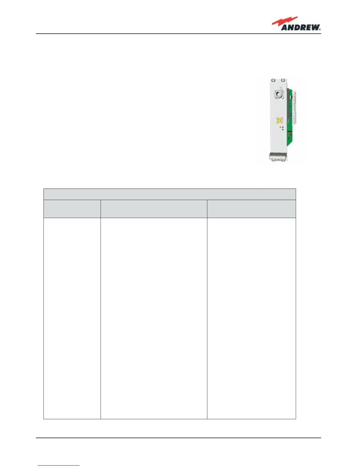
The Power Limiter (TMPx-10): it monitors the DL power coming from the
BTS and attenuates it by 10 dB in case it surpasses a programmable
threshold level.
The TMP2-10 Power Limiter is for 2G and 2.5G signals, working at 900
MHz and 1800 MHz.
The TMP3-10 Power Limiter is for 3G signals.
Both modules are 7TE wide and 4HE high.
Table 2.2 shows an overview of the basic
components of the ION-B Master Unit.
Fig. 2.11 TMPx-10 card
Basic components of ION-B Master Units
Unit name/
Module name
Description Dimensions, H x W ( x D)
TPRF31
TPRN04
TPRNx4
TFLNx
TLCN 2
TLCN 4
TBSI 2-30
TDPNx
TLDNx
TLTNx
TMPx-10
Fast MiniRack
Passive subrack
Active subrack
Master Optical TRX
2-way splitter
4-way splitter
Adjustable attenuator
UL/DL duplexer
Dual band coupler
Tri band coupler
10 dB power limiter
19” x 1HE x 286mm
19” x 4HE x 350mm
19” x 4HE
7TE x 4HE
7TE x 4HE
7TE x 4HE
7TE x 4HE
7TE x 4HE
7TE x 4HE
7TE x 4HE
7TE x 4HE
Table 2.2: Overview of the components and accessories for the ION-B master unit
 Loading...