94
03/2010 Rev. 0.1
03/2010 Rev. 0.1
95
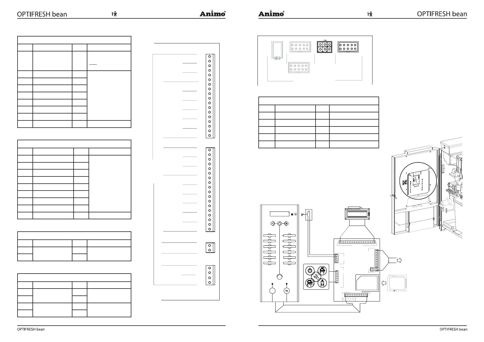
7.1.2 Main circuit board exits
Connector J2
Pin Motor Colour Comments
17-18 Brewer / Mixer 1
Black
Correct direction of rota-
tion = red wire (+24VDC)
NOT on red spot of the
Brewer Motor
15-16 Mixer 2 Violet
Take care to rotate in
the right direction!
Shared +24 DC (red wire)
on red spot on Mixer and
Ingredients Motor.
13-14 Mixer 3 Pink
11-12 Grinder signal 1 Brown
9-10 Ingredient Motor 2 Green
7-8 Ingredient Motor 3 White
5-6 Ingredient Motor 4 Yellow
3-4 Ingredient Motor 5 Grey
1-2 Ingredient Motor 6 -
Connector J4
Pin Valve Colour Comments
17-18 KW 1 (inlet valve) Violet
Red wire is a shared
(24VDC) connection
15-16 KW 2 -
13-14 KW 3 -
11-12 DV 1 (brewer valve) Brown
9-10 DV 2 (mixer 2 valve) White
7-8 DV 3 (mixer 3 valve) Yellow
5-6 DV 4 (hot water tap) Green
3-4 DV 5 Grey
1-2 DV 6 (cold water tap - -
Connector J15
Pin Motor Colour Comments
2
Ventilator
Red
1
Orange
Connector J6
Pin Relay Colour Comments
4
Power relay (element)
Red
3 White
2
-
-
-
1
7.1.3 Main circuit board communication
Communication
Conn Comments
G13 Coin tester NRI G13
MDB Coin changer NRI C
2
CSI Future port
RS232 Future port
USB Future port
7.2 Interface / Display
The interface ( g. 29) connects all components found
inside and on the door with the main control unit via a
at cable.
18
17
16
15
14
13
12
11
10
9
8
7
6
5
4
3
2
1
MIX/BR
MIX2
MIX3
IM1
IM2
IM3
IM4
IM5
IM6
2
1
KW1
KW2
KW3
DV1
DV2
DV3
DV4
DV5
DV6
18
17
16
15
14
13
12
11
10
9
8
7
6
5
4
3
2
1
2
1
HEATER
RELAIS
DOSING VALVESVALVES
INGREDIENT MOTORSMIXERS
4
3
FAN
INLET
OUTPUTS
J15
J6
J2
J4
H1
H2/3
Fig. 27
G13
MDBCSI
OPTIONAL
COMMUNICATION
USB
RS232
Fig. 28
SD Memory Card
Animo OptiFresh
SD-READER
KEYSWITCH
MAIN BOARD
DISPLAY
SERVICE KEYBOARD
J1
JP2
JP3
J3
J14
J2
TO MAIN PC BOARD
KEYBOARD
J4
JP4
Fig. 29a
Fig. 29



 To Next Page