96
03/2010 Rev. 0.1
03/2010 Rev. 0.1
97
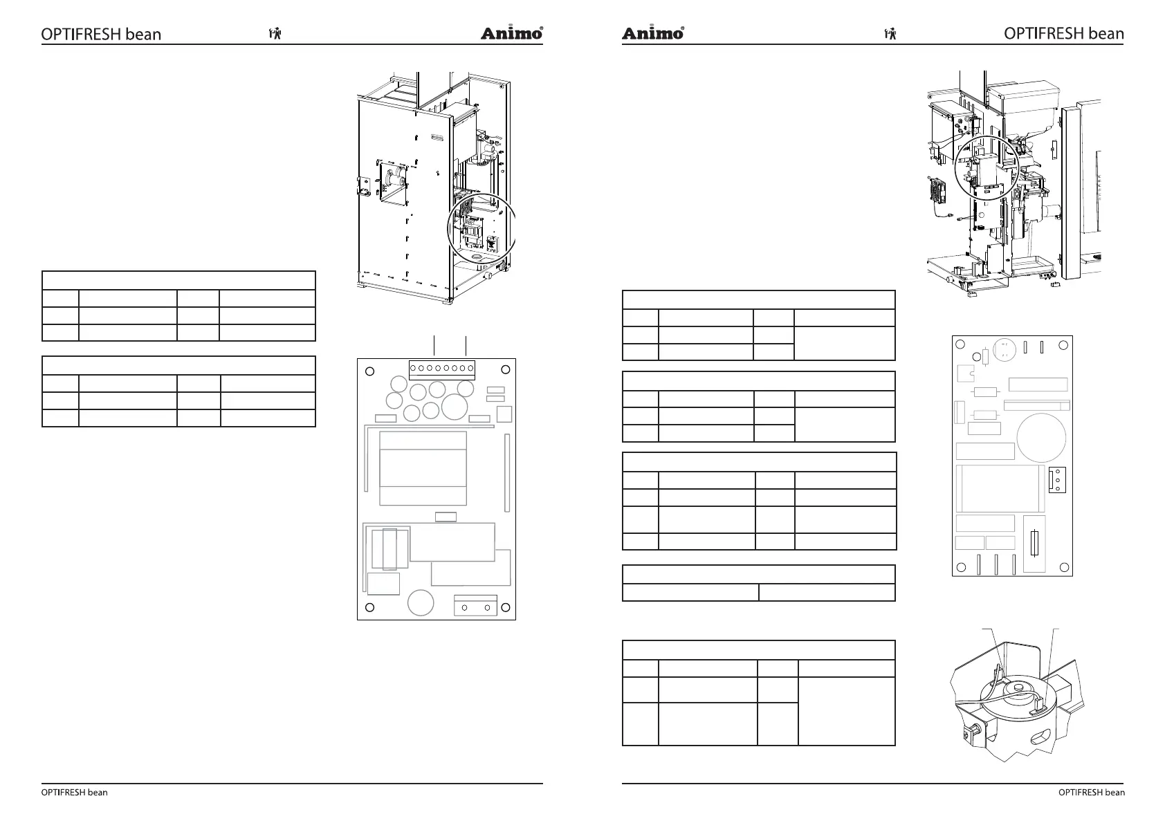
7.3 Power supply
The 24 V DC power supply ( g. 30) consists of a
24V DC 65W switch mode power supply and can be
accessed by removing the rear plate.
The power supply is located under the main
circuit ( g. 30a).
During an overload the power supply automatically
switches off. Reset the power supply by turning the
main switch off and on.
7.3.1 Connections
Connector TB2 24Vdc
Pin Colour Comments
1 230Vac Neutral blue
3 230Vac Phase yellow
Connector TB1 100-240Vac
Pin Colour Comments
1-2 24Vdc + Red
6-7 24Vdc - black
7.4 Grinder PC board 230Vac / 230Vdc
This grinder PC board (Fig. 31) convert 230Vac (AC)
trough a recti er in 230Vdc (DC) that drives the grinder
motor.
The IM1 signal (24Vdc) of the main PC board is fed to
connector J5-J6 (red LED turns on). This signal switch
on the grinder motor by a triac.
This PC board is accessible through the rear to
disassemble.
Fuse 3,15 A T (Art. No. 02580) ; to protect the grinder
motor.
7.4.1 Connections
24Vdc ingredient 1 signal
Pin Colour Comments
J5 24Vdc + red
polarity not important
J6 24Vdc - brown
230Vdc
Pin Colour Comments
1 230Vdc + red
polarity important !
3 230Vdc - black
230Vac
Pin Colour Comments
J2 230Vac Nul blue
J3 PE (aarde) yellow/
green/
J4 230Vac Fase brown
Fuse F1
3,15A slow Art.No. 02580
Grinder motor 230Vdc
Pin Colour Comments
230Vdc + red
Please pay attention,
for right direction.
+24dc (red wire)
according drawing
230Vdc - black
Fig. 30a
+24V GND
100-240 Vac
1
TB1
TB2
Fig. 30
Fig. 31a
F 3,15A T
230Vac
J6J5
LED
J3J2 J4
PE
F1
Grinder
motor
230Vdc
24Vdc
grinder
signal
LN
+
_
J7
Fig. 31
Fig. 31b
+
RED
-
BLACK



 To Next Page