UNION SWITCH & SIGNAL Microlok II System Startup, Troubleshooting, and Maintenance
6-6 September 2000 SM-6800C Rev. 2.5
Event
Number
Event Class Class Description
24 MLKII Serial Master Class Not generated by Microlok II
25 MLKII Serial Slave Class Not generated by Microlok II
26 CAB Serial Master Class Not generated by Microlok II
27 CAB Serial Slave Class Not generated by Microlok II
28 Non-Vital Output Class Errors/Events related to the NV.OUT32 board
29 Non-Vital Input Class Errors/Events related to the NV.IN32 board
30 LCP Driver Class Errors/Events related to the NV.IN32.OUT16 board
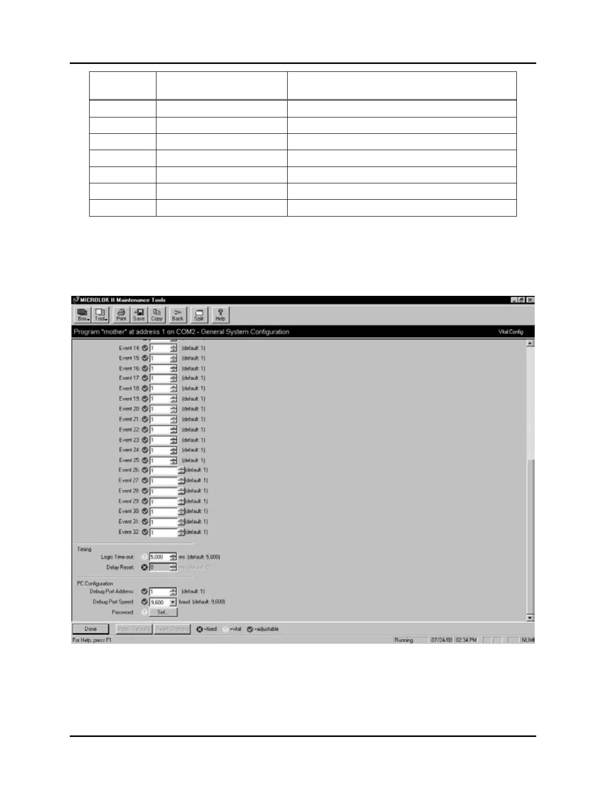
3. You must scroll the screen down to access the remaining configuration options on this
display (see following page). The Timing parameters are set in the application program.
These parameters specify delay periods (in milliseconds) that are used by the system during
normal operation (Logic Time-out) and following a manual reset of the system (Delay Reset).
 Loading...