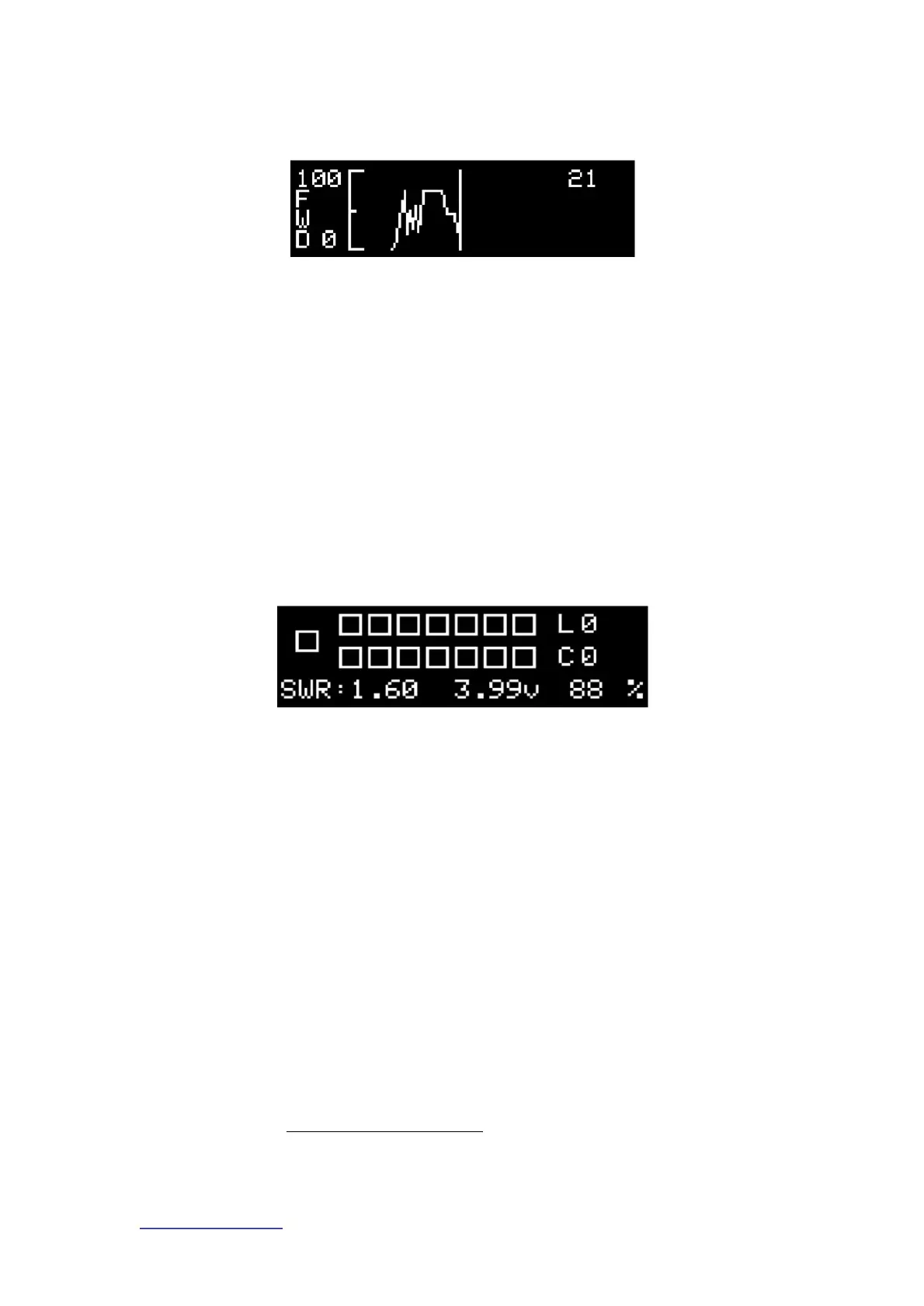
4) Forward power line graph interface
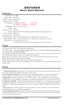
This function interface mainly displays the switching status of all relays, SWR is the standing wave value (range 0.0-9.9), L is the voltage
This function interface mainly displays the change trend of positive power in real time in the form of a line graph, and the realistic range is 0-10W
Inductance value (unit: ÿH ), C is capacitance value (unit: pF).
or 0-100W
Through this interface, you can know the capacitance value and inductance value after tuning, and at the same time, you can graphically observe the continuation of the operation.
ÿ
Location and quantity of appliances.
If the actual transmission power or the power detected by the standing wave meter deviates from the power detected by the tuner, you can press the advanced operation
"3.99v" in the center of the bottom of the screen is the current battery voltage, and "88%" is the current remaining power.
3.6 chapter [FIX PWR] to calibrate. You can also modifyÿFIX RADIOÿAdjust the radio power type and modify here
The user storage mode is a mode with multiple stored tuning results, and in this mode, the storage result selection interface is displayed by default after power on.
maximum value.
5) Relay status interface
In the transmission process, the power value, standing wave value, line graph, relay status and other interfaces can be displayed.
2.6 User storage mode function interface introduction
http://www.antuner.com
BI3QWQ
ANTUNER only researches ultra-small, portable radio peripherals, and completely develops software and hardware at the bottom
Positive Power Trend
Relay switch status
Machine Translated by Google