AR7030 OPERATING MANUAL PAGE 11
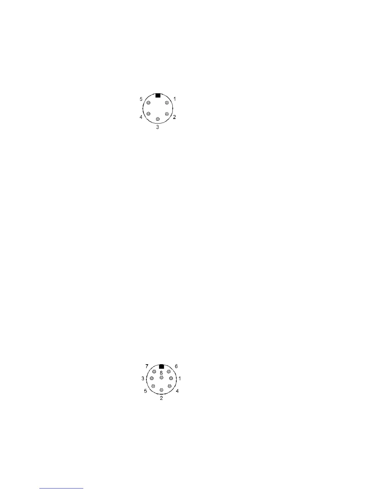
5-15 Computer control socket
This accessory socket is used for connection to a computer
via RS232 link.
The socket is a 5-pin / 240° DIN with the following
connections:
Pin 1 External supply output available,
nominal 14V @ 100mA MAX
Pin 2 RXD
Pin 3 TXD
Pin 4 No connection
Pin 5 GROUND
Connection to a PC should be as follows:
AR7030 PC 9-D PC 25-D
pin 2 pin 3 pin 2
pin 3 pin 2 pin 3
pin 5 pin 5 pin 7 (GND)
5-16 Auxiliary equipment socket
This accessory socket is used for connection to tape
recorders and data decoders. Two audio outputs are
provided unaffected by volume and tone settings. A mute
input and a 455 kHz IF output are also present.
The socket is of an 8-pin DIN, circular configuration with
pin 8 being at the centre. The connections are as
follows:
Pin 1 MUTE - ground to mute the receiver
(in conjunction with a transmitter)
Pin 2 GROUND
Pin 3 External supply output available,
nominal 14V @ 100mA MAX
Pin 4 Auxiliary audio output (LEFT) 0-800mV
from 1kohm
Pin 5 Auxiliary audio output (RIGHT) 0-800mV
from 1kohm
Pin 6 Aux control relay contact A
(for tape recorder motor control)
Pin 7 Aux control relay contact B
(for tape recorder motor control)
Pin 8 455 kHz IF output -20dBm / 50 ohms
The aux relay can only be used for
low voltage control, NEVER
CONNECT MAINS TO THE AUX
RELAY CONTACTS.
5-17 DC power input
This is a 2.1mm coaxial power socket designed to accept
external d.c. input from an ac adapter. See section 4-3
for supply details.
5-18 External speaker output socket
This 3.5mm mono jack socket provides audio output to
drive an external speaker unit. Connection to this socket
automatically disables the internal speaker but not a
headphone if connected to the front panel socket.
An external speaker should have a minimum 8 ohm
impedance and power handling of 2 watts or greater.
5-19 Display contrast adjustment
This rotary control adjusts the LCD display contrast and
viewing angle. Adjust this for optimum display readability
- it may need re-adjusting if the viewing angle is changed
or if there is a significant change in temperature. The
normal control position will often be slightly less than fully-
clockwise.
5-20 Ground (chassis) connection
Ground connection for an external RF earth. This often
reduces noise.
5-21 Wire aerial connection
Connect a long wire aerial to this terminal.
5-22 Antenna selection switch
This slide switch is used to select the aerial connection
and function: 50 OHM, WHIP or WIRE.
5-23 50 OHM aerial socket
50 OHM SO239 socket designed for connection to
unbalanced 50 OHM aerials with coaxial feeders, or, with
the selection switch in the WHIP position, a telescopic
aerial.