EasyManua.ls Logo

AOR AR2700 User Manual

AOR AR2700
64 pages
To Next Page IconTo Next Page
Page #1 background imageLoading...
Page #1 background image
AR2700 operating manual
1
(1) Introduction & accessories
Thank you for purchasing the new AOR AR2700 wide band receiver.
This operating manual is divided into many sections and presented in a logical
order assuming that it will be read section by section following the examples.
However, if you are familiar with the operations of modern multi-function
receivers you may proceed directly to section 6. Many phrases are
repeated through the manual, while this may make the text a little repetitious, it
should provide clear instructions if you refer directly to a specific section.
Every effort has been made to make this manual correct and up to date. Due
to continuous development of the receiver and by error or omissions,
anomalies may be found and this is acknowledged.
Most apparent faults are usually due to accidental misoperation of the receiver,
carefully read all of the manual before deciding to return the receiver for repair.
Although carefully designed, this receiver (like all receivers) suffers from a
degree of internal noises known as spurii. They are a product of the receiver’s
circuitry and do not represent a fault.
This manual is protected by copyright AOR LTD 1995. No information
contained in this manual may be copied or transferred by any means without
the prior written consent of AOR LTD. AOR and the [AOR] logo are trade
marks of AOR, LTD. All other trade marks and names acknowledged. E&OE.
© 1995 AOR LTD.
Operating manual Conventions and special notes
Where text appears in [SQUARE BRACKETS] the keys are to be pressed
exactly as shown.
For example: [1] [4] [5] [ENT]
Means press the 1 key followed by the 4 key followed by the 5 key
followed by the ENTER key.
The arrow keys to the lower left of the keypad are referred to as UP / DOWN or
[UP] [DOWN] keys.
Words contained in speech marks “BANK” refer to indications displayed on the
Liquid Crystal Display.
Where memory banks etc are empty the indication “- - -” is often displayed.
[2ndF] function key: The function key [2ndF] provides access to additional
facilities via the numeric keypad. The function key should be momentarily
pressed only (so that the legend “2ndF” appears in the top left corner of the
LCD) before another numeric key is pressed... do not hold the function key
in while pressing other keys.

Table of Contents

Other manuals for AOR AR2700

Question and Answer IconNeed help?

Do you have a question about the AOR AR2700 and is the answer not in the manual?

AOR AR2700 Specifications

General IconGeneral
BrandAOR
ModelAR2700
CategoryReceiver
LanguageEnglish

Summary

(1) Introduction & accessories

Operating manual Conventions and special notes

Explains conventions like bracketed keys and speech marks used in the manual.

1-1 Accessories supplied

Lists the items included with the AR2700 receiver.

(3) Major features

General

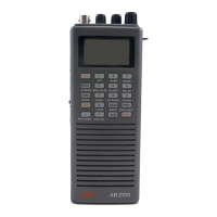
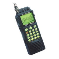
Provides an overview of the AR2700's advanced features and construction.

Frequency coverage and modes

Details the receiver's frequency range and supported reception modes (AM, NFM, WFM).

Auto-Mode tuning

Describes the automatic selection of mode and channel step based on bandplan data.

Wide variety of search & scan facilities

Highlights the flexibility of search and scan functions using various parameters.

(4) Precautions

4-1 Location

Advises on suitable environments and avoiding hazards like sunlight, heat, and liquids.

4-2 Looking after your receiver

Provides guidance on cleaning and maintaining the receiver's physical condition.

4-3 Power requirements

Specifies the voltage, current, and battery types required for operation.

4-4 NiCads and charging

Details the charging procedure and care for NiCad batteries to prevent memory effect.

4-5 Aerial (antenna) connection

Explains how to connect aerials, including types and considerations for sensitivity.

(5) Controls and functions

5-1 Aerial (antenna) input

Details the BNC socket for connecting aerials.

5-2 Earphone / speaker connection

Explains the 3.5mm socket for audio output devices.

5-3 DIAL - tuning control / selector

Describes the rotary control used for frequency tuning and data selection.

5-4 Squelch control

Explains how to adjust the squelch to minimize background noise.

5-5 Volume control

Describes the control for adjusting the audio output level.

5-6 Liquid Crystal Display (LCD)

Details the display features, legends, and indicators.

5-7 Keypad

Explains the layout and function of the front panel keypad.

5-8 Internal loudspeaker

Notes the presence of an internal speaker and its disconnection when external audio is used.

5-9 [2ndF] Function key

Explains how to access secondary functions using the [2ndF] key.

5-10 [MONI] monitor key

Describes the monitor key used to defeat squelch for weak signals.

5-11 [K.LOCK] keypad lock key

Explains the keypad lock feature to prevent accidental operation.

5-12 microprocessor reset switch

Details the soft reset function for troubleshooting operational issues.

5-13 DC 12V Charging / external power connection

Explains the DC socket for charging and external power input.

5-14 RS232C REMOTE connector

Details the connector for computer control and data transfer.

5-15 BATTERY compartment

Explains how to access and install batteries in the compartment.

(6) Basic manual operation of the receiver

Operating manual conventions

Explains conventions used in the manual, such as key press notation.

6-1 Before starting

Outlines initial steps before operating the receiver, like charging batteries.

6-2 Switching On

Provides instructions on how to power the receiver on and set initial controls.

6-3 Entering a frequency through the keypad - VFO (MANUAL) MODE

Details how to input frequencies using the keypad in manual mode.

6-4 Correcting frequency input

Explains how to correct errors during frequency data entry.

6-5 Changing frequency using the [UP] [DOWN] keys and [DIAL]

Describes methods for changing frequency and tuning.

6-6 Changing frequency STEP size (PROGRAM)

Explains how to select and change the tuning step size.

6-7 Changing receive mode (PROGRAM)

Details how to select and change the receive mode (AM, NFM, WFM).

6-8 [ATT] Attenuator ON/OFF

Explains how to use the attenuator to reduce signal strength and prevent overload.

(7) Memory banks & channels

7-1 Storing receive data into memory - memory input in MANUAL mode

Guides on storing frequencies and settings into memory banks.

7-2 Automatic memory incrementation

Explains how the receiver automatically moves to the next channel for storage.

7-3 Memory recall - Recalling receive data from memory

Details how to retrieve stored frequencies and settings from memory.

7-4 Transfer of memory channel to VFO

Describes transferring memory data to the VFO for tuning.

7-5 Memory over-write

Explains how to update or replace existing memory entries.

7-6 [M.DEL] - deleting individual memory channels and banks

Provides instructions on how to delete memory channels and entire banks.

(8) Priority operation

8-1 Entering data into the priority channel

Explains how to set a priority frequency for monitoring activity.

8-2 Activating & deactivating priority

Details how to enable and disable the priority watch feature.

8-3 Programming priority sampling interval

Guides on setting the time interval for checking priority frequency activity.

(9) SCAN - scanning memory channels & banks

9-1 Starting to SCAN, considerations...

Provides tips for optimizing scan speed and effectiveness.

9-2 SCANNING a memory bank...

Explains how to initiate scanning of stored memory channels.

9-3 Memory transfer to VFO

Describes transferring a scanned channel's data to the VFO.

9-4 Selecting a single memory bank to scan

Explains how to choose a specific bank for scanning.

9-5 Memory bank linking

Details how to link multiple banks for scanning as a group.

9-6 Scanning a memory bank which is not selected in BANK LINK

Explains how to scan individual banks bypassed by bank linking.

9-7 SCAN channel PASS - CH PASS (lockout), general outline

Introduces the channel pass (lockout) feature to skip unwanted channels.

9-8 Memory scan PASS while scanning

Explains how to pass (lockout) a channel during an active scan.

9-9 Memory CHANNEL PASS & review using Memory Recall mode

Guides on managing channel pass status via memory recall.

(10) DELAY and PAUSE facility in scan and search modes

10-1 DELAY time

Explains the delay parameter that affects time on active channels after signal loss.

10-2 PAUSE time

Details the pause parameter for holding on active channels during scan/search.

(11) SEARCH - manual & program search banks and PASS

11-1 Manual SEARCH

Describes how to perform a basic search between defined frequency limits.

11-2 FREQUENCY PASS in search mode

Explains how to skip frequencies during a search using the PASS feature.

11-3 Program search banks

Details how to save and use programmed search banks.

11-4 Reviewing program search upper and lower limits

Guides on viewing and identifying programmed search bank limits.

11-5 Programming and reprogramming PROGRAM SEARCH BANKS

Explains how to create or modify search bank parameters.

11-6 Program search bank linking

Details how to link search banks for sequential scanning.

11-7 Searching a search bank which is not selected in BANK LINK

Explains how to scan individual banks bypassed by bank linking.

(12) Sleep timer - automatic power Off

12-1 Enabling SLEEP time

Explains how to activate the automatic power-off sleep timer.

12-2 Defining the SLEEP time period

Guides on setting the duration for the automatic power-off timer.

(13) Optional VOICE recording facility

13-1 Initialising the record option

Details the initial setup for the optional voice recording chip.

13-2 Recording

Explains how to make a 20-second digital recording of transmissions.

13-3 Play back

Guides on replaying previously recorded transmissions.

(14) Remote control using a computer (RS232C)

14-1 Setting the RS232 parameters

Explains how to configure RS232 communication settings for computer control.

(15) Clone (copy) data between two AR2700 receivers

15-1 Transferring data by CLONE

Details the process of copying data between two AR2700 receivers.

(16) Trouble shooting

16-1 Microprocessor reset

Describes different methods for resetting the receiver's microprocessor.

16-2 Other possible operational problems

Addresses common issues like weak signals and frequency jump errors.

16-3 Other LCD indications and error messages

Explains various LCD messages, including beeps, boops, and error codes.

16-4 Special functions

Covers advanced settings like squelch detect and PLL lock times.

(17) Optional accessories

RU2700 VOICE RECORDING Chip

Optional chip for recording and playback of 20 seconds of transmission.

IF-ADP & CU8232 Interface

Adaptor and interface for computer control and cloning data.

DA3000 VHF-UHF discone aerial

High-performance VHF-UHF discone aerial for wide frequency coverage.

ABF125 VHF civil airband filter

Filter to reduce interference from powerful VHF transmitters.

(18) Specification

Frequency and Mode Specifications

Covers frequency range, coverage, and supported reception modes.

Sensitivity and Tuning Steps

Details receiver sensitivity across different bands and selectable tuning step sizes.

Memory, Search, and Pass Channel Capacity

Specifies memory channel count, banks, search banks, and pass channels.

Operational Parameters

Includes VFO, priority channel, scan/search rates, aerial input, and audio output.

Power and Current Consumption

Outlines power requirements (battery and external) and current draw.

Related product manuals