7032 SOUTH 196th - KENT, WA 98032 - (253) 872-0141 / FAX (253) 872-8710
OPERATION / MAINTENANCE MANUAL
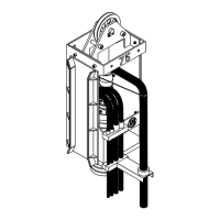
MODEL 50 VIBRATORY HAMMER WITH MODEL 260 POWER UNIT
Table of Contents
Page
Revision Record ................................................................................................... i
Preface ................................................................................................................. ii
Table of Contents................................................................................................. iii
Safety Precautions............................................................................................... v
Illustration List ...................................................................................................... vi
Table List .............................................................................................................. vi
Warranty ............................................................................................................... vii
I. GENERAL INFORMATION .............................................................................................. 1-1
I-1. Machine Features ............................................................................................. 1-1
I-2. Machine Specifications ..................................................................................... 1-2
A. Model 50 Vibro..................................................................................... 1-2
B. Model 260 Power Unit ........................................................................... 1-2
I-3. General Description of 50 Vibro ........................................................................ 1-3
A. Suppressor Housing .............................................................................. 1-4
B. The Vibrator Gearbox ............................................................................ 1-5
C. Clamp Attachment ................................................................................ 1-6
D. Optional Attachments ........................................................................... 1-7
I-4. General Description of Model 260 Power Unit ................................................... 1-8
II. MAJOR COMPONENT DEFINITION ............................................................................... 2-1
II-1. Component Identification.................................................................................. 2-1
II-2. Hose Identification ........................................................................................... 2-3
II-3. Model 260 Power Unit Skid Identification ......................................................... 2-4
II-4. Quick Disconnect Couplings ............................................................................ 2-5
II-5. Tool Set Identification.................................................................... .......... 2-6
II-6. Caisson Clamp Identification ............................................................................ 2-7
III. LOADING AND UNLOADING ........................................................................................ 3-1
III-1. Model 50 Vibratory Hammer............................................................................ 3-1
III-2. Model 260 Power Unit ..................................................................................... 3-1
III-3. What to do if damaged during shipment .......................................................... 3-1
IV. PREPARATION AND OPERATION ............................................................................... 4-1
IV-1. Rigging of Vibratory Hammer.......................................................................... 4-1
IV-2. Installing the Clamp Attachment..................................................................... 4-1
IV-3. Plumbing the Vibro Hoses to the Power Unit .................................................. 4-2
IV-4. Filling Vibrator Pressure Hoses ...................................................................... 4-3
IV-5. Bleeding Clamp Attachment Hydraulic Hoses ................................................ 4-3
IV-6. Precautions and Rules for Operation .............................................................. 4-4
IV-7. Relief Valve Settings Prior to Operation - Model 260....................................... 4-5
IV-8. Shut-down Procedures ................................................................................... 4-5
IV-9. Operation of the Remote Control Pendant ...................................................... 4-6
IV-10.Normal Steps to Operate Vibrator.................................................................. 4-6
V. MAINTENANCE .............................................................................................................. 5-1
V-1. Daily Maintenance Required Prior to Operation ............................................... 5-1
V-2. Checklist After Power Unit Engine Has Started ............................................... 5-1
V-3. Maintenance and Adjustments:....... (75 Hours).............................................. 5-2
V-4. Maintenance and Adjustments:....... (Eccentric Bearings) ............................ 5-2
V-5. Maintenance and Adjustments in Severe Conditions .......................................
5-2
V-6. Lubrication ...................................................................................................... 5-2
A. Vibratory Gearbox ................................................................................. 5-2
B. Clamp Attachment ................................................................................ 5-2
Page iii