7032 SOUTH 196th - KENT, WA 98032 - (253) 872-0141 / FAX (253) 872-8710
OPERATION / MAINTENANCE MANUAL
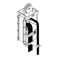
MODEL 50 VIBRATORY HAMMER WITH MODEL 260 POWER UNIT
VII-2. Electrical Circuitry
The following are descriptions of components that make up the Electric Circuitry of the APE Model
260 Power Unit.
VII-2A.
Diesel Engine
The HYDRAULIC POWER UNIT is powered by a 4 stroke compression ignition diesel engine.
Two 12 volt (4D) batteries provide 24 volts for starting the engine and running the electrical
controls.
VII-2B. Controls: (Understanding How They Work)
1. Engine Control Switch "OFF/ON/START"
The ENGINE CONTROL SWITCH is used to start and stop the diesel engine. Turning it to
"ON" turns on all power to the panel. Turning to START energizes the engine starter so-
lenoid which activates the starter motor which turns the diesel engine flywheel and causes
the engine crankshaft to turn which, through various mechanical actions, acts on the fuel
pump. As the engine turns, the fuel pump injects fuel into the combustion chamber of each
piston cylinder at timed intervals and as the engine continues to crank, fuel and air is
compressed in the combustion chamber by each piston as it comes up on the compression
stroke. As the pistons compress fuel and air, the fuel and air mix into a combined gas that
ignites under pressure when each piston nears the top of its stroke the gas explodes, forcing
the piston downward and converts thrust into torque via a connecting rod pinned to the piston
and mounted to a crankshaft. When the piston reaches the bottom of the cylinder, it begins
its upward travel and an exhaust valve at the top of the cylinder opens, forcing unburned
gases out. When the piston reaches the top, the exhaust valve closes and an intake valve
opens as the piston travels back downward. The piston sucks new air into the combustion
chamber while the fuel injector adds fuel. These four cycles of intake, compression, ignition
and exhaust continue until the engine fuel delivery is cut off.
Once the engine is rotating on its own power, the switch is released. The switch returns to
the "ON" position because it is spring loaded in that direction. To turn the engine off, the switch
is turned to the "OFF" position, which sends a grounded signal that activates the ENGINE
SAFETY SHUT DOWN SWITCH which then cuts power to the fuel solenoid and stops the
engine.
2. "LOCAL/REMOTE" Switch
The LOCAL/REMOTE SWITCH is used to allow the operator to control the power unit from
either the CONTROL PANEL or the REMOTE HAND HELD PENDANT. The LOCAL /
REMOTE SWITCH must be in the LOCAL position to start the engine.
VII. MODEL 260 POWER UNIT (Continued...)
Page 7-4