© Ikonix USA
12
Models
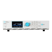
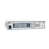
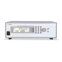
8505 8512 8520 8540
System Parameters & Features
Calibration
1. Built-in software and external calibrated meters
2. Adjustments made through front panel
Software Feedback Control Method
(ADJ)
PID Control - Software Feedback. 12Bit A/D converter drives the amplifier.
Meter Refresh Rate
300ms @ 5.0-39.9Hz
100ms @ 40.0-1200Hz
Operation Key Feature Soft key, Numeric key, Output ON/OFF/Reset key, Rotary Knob
Hardware Interlock Standard Hardware Interlock with direct control of amplifier output relay.
PLC Remote
Two DB9 connectors on the rear panel for Signal Input and Output
Input: Output ON, Output OFF/RESET, Interlock, File Recall M1 through M7, Trigger.
*Minimum 6s pulse width for all Remote Input Keys
Verify: If PLC = Verify when selecting M1-M7, the test file will load but TEST signal will be
required to initiate the output.
Output: Fail, Test-in-Process
*Output relay contact rating is 1A/125V
Output Type AC, DC, AC+DC
Voltage Sense Function (Vs) INT / EXT (Low range: 5V / High range: 10V)
Inrush Current 4 times current rating
Enhanced Overload Capacity Over current 110% can hold for 1000 ms without protection
Interface
(Programmable Option)
Standard: USB & LAN, Optional: GPIB
SCPI bus commands for full instrument control.
Mimic Mode option for APT 6000, 7000 & 300XAC series power sources.
Alarm Volume Setting Range: 0-9; 0=OFF, 1 is softest volume, 9 is loudest volume
Graphic Display 4.3” TFT LCD (resolution: 480 x 272)