28 Ultrasound Controller Manual
Connecting the level sensor
The Level Sensor cable may not be
extended. Maximum cable length, see
Level Switch manual. The unshielded
part of the cable should be no longer
than 40mm. The shield shall if possible
be connected to ground via shielded
cable glands. To minimize the risk of
electric interference and noise,
especially in ex-installation, see Electric
Noise page 10.
If D72 is mounted inside a metal
cabinet it is good to connect D72 to the
cabinet (ground) using grounded cable
glands for the Level Switch cables. If
grounded cable glands are not used
then terminal 16 on the D72, DP72,
GS72 or terminal 19 on D128 can be
connected to the cabinet instead.
Mounting the Sensor for level
and the velocity sensor
Level Sensor 1 or Level Sensor 3
measures the level and it is a Level
Switch type of sensor which is mounted under the bottom of the container. The ultrasound travels
through the bottom and it is important the sound can pass easily through the bottom into the
liquid. It depends on the wall material and thickness. Steel or glass bottom 1,2mm - 7 mm are ok.
Most plastics let sound trough well except polypropylene and fiber reinforced plastics. For
stainless steel, best result is achieved with bottom thickness being a multiple of 1,42mm
(resonance at 2MHz half wavelength). Stainless steel bottom thickness 7mm 5,7mm 4,3mm
2,8mm or 1,4mm is ok at 2MHz which is the best frequency for the Level Switch. For other
thicknesses other less ideal frequencies will be chosen by the Ultrasound Controller. The
thickness of the bottom also determines how well low levels can be measured. When the bottom
is thick, vibrations within the wall decays slowly and measurements of low levels becomes more
difficult. Minimum level that can be measured depends on the bottom thickness and material.
The ultrasound beam is narrow (beam angle is about 10˚) so the level sensor must be aimed in
such a way that the echo from the surface is properly returned back
to the level sensor. If the bottom is not horizontal, silicone sealant
can be used to glue the Level Switch at an angle, see below. See
Level Switch manual how to glue the sensor. The GF90 contain
both level and velocity sensors. Sound velocity varies with liquid
and temperatures. The Level Switch used as a sensor for velocity
is placed low on the container wall. It measures and compensates
for sound velocity changes. It also makes level switch
measurement which can be used to limit the measured level for
extra reliability.
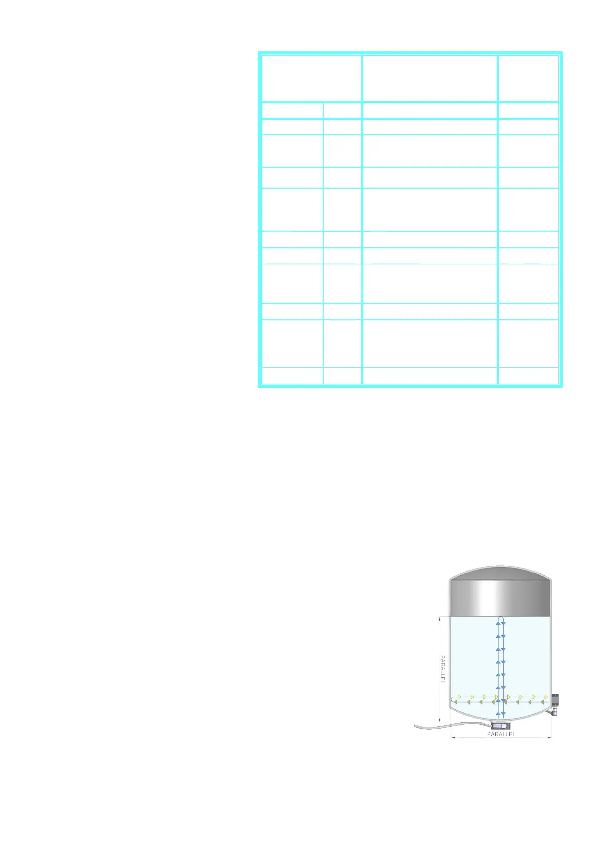
Mounting the velocity sensor
Velocity Sensor 2 and Velocity Sensor 4 is a Level Switch-type of
sensor which is used to measure the sound velocity of the liquid. It should be mounted on the
container wall to measure the echo from the opposite container wall. If possible near the bottom