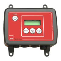
Installing Ultrasound Controller DP72, GP72
The Ultrasound Controller DP72 and GP72 should be protected
from dust and water. It is made to be attached to a DIN-rail, to
which it snaps easily and can be removed by pushing up and
bending the top out. Usually it is installed in an electric cabinet.
The green connector terminals can be removed by pulling the
connector out. Connections for terminal 1-7 and D-sub, see
table. Connections for terminal 8-17 depend on the selected
mode, see table in the corresponding chapter.
The Ultrasound Controller should be installed in accordance
with national regulations. A person with the required knowledge
should perform the installation.
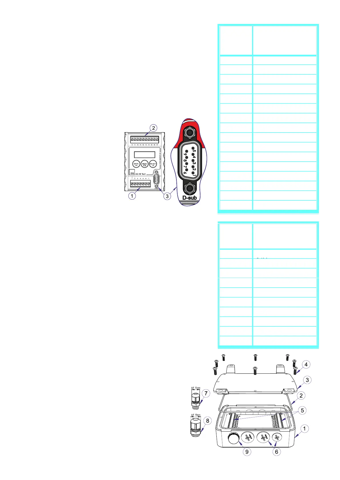
Installing Ultrasound Controller D128, G128
The Ultrasound Controller D128 and G128 is protected
according to IP65 and can be installed outside a protecting
cabinet. The bottom plate must be removed in order to access
the terminals. Remove dummy covering and insert cable
glands as needed. There are 3 small and 4 big cable glands.
There should be only one cable in each cable gland to achieve
full IP65 protection. The pressure compensation element can
be moved to different place but must not be removed
completely. Make sure the gasket is in place when screwing
the bottom plate. Connections for terminal 1-10, see table.
Connections for terminal 11-20 depend on the selected mode,
see table in the corresponding chapter.
The Ultrasound Controller should be installed in accordance
with national regulations. A person with the required knowledge
should perform the installation.