AQUA SALT
+
MAINTENANCE AND INSTRUCTION MANUAL
Salt chlorine genera ENGLISH
ADSP7000753 rev. 5.0 09/07/2019 12/51
3.1.3
Electrolytic Cell and
control box
installation
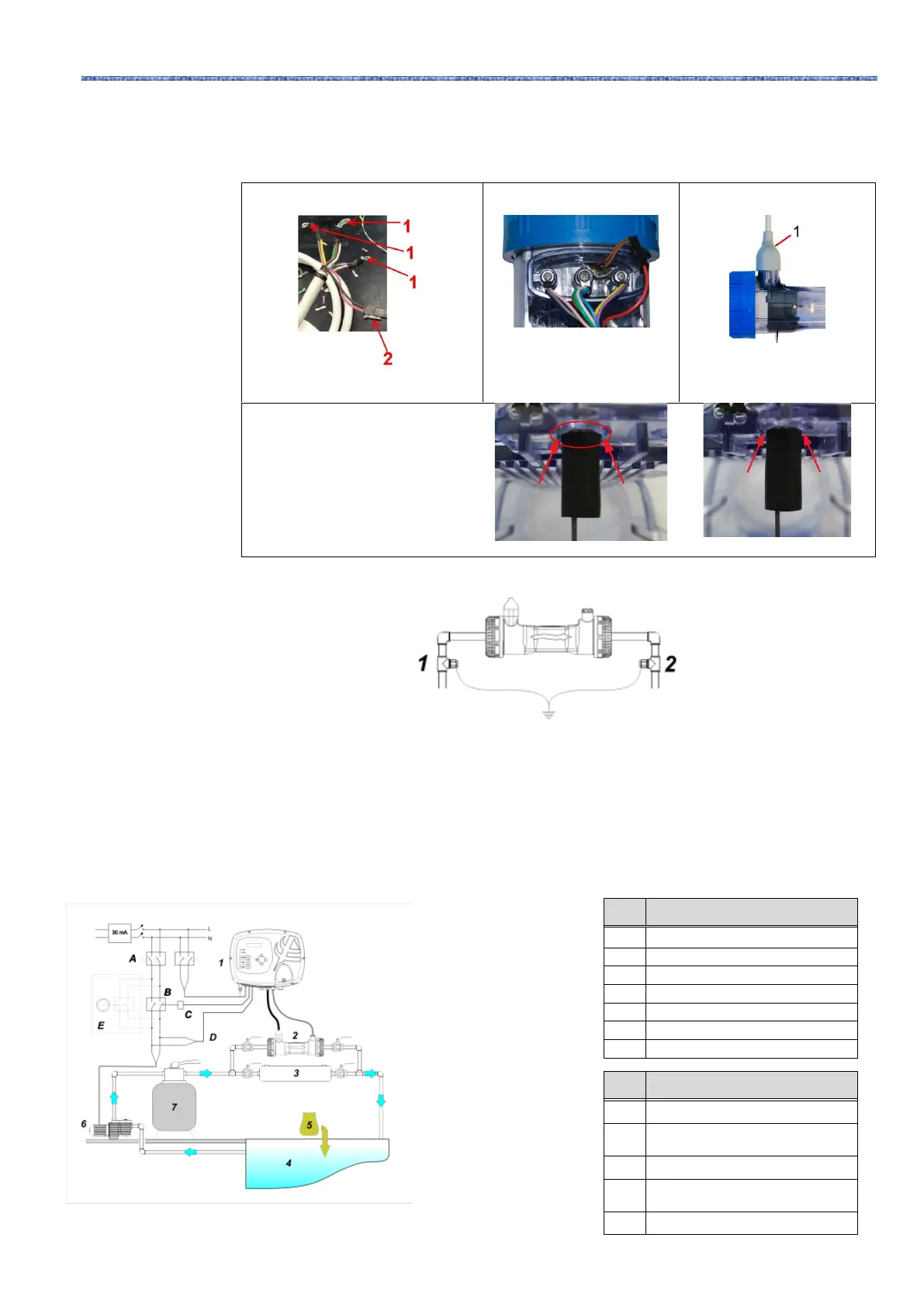
At this point, it is necessary to connect the electrolytic cell to the control box by connecting flow
sensor/pressure, temperature probe and the part that provides voltage to the plates, as indicated in
the image sequence below:
1.
1 → cell supply voltage
2 → temperature sensor
2.
Connect the temperature
probe.
3.
Insert the white rubber cap
to cover the connection
wires..
CAUTION:
Check the correct
tightening of the rubber
protection, which must
adhere to the cell, to
ensure perfect sealing and
PIN protection.
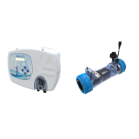
The kit prevents electric noise from plastic pipes and tubes, which may cause wrong indications
on measurement instruments, especially pHmeters and Rxmeters. Please install the grounding
electrodes upstream (1) and downstream (2) the cell and connect them to a ground lead.
✓ Connect to ground circuit separate and independent from the main circuit.
3.1.5
Installation example
The sample installation diagram below refers to the standard chlorine generator.
AQUA SALT
+
control system
Pool (max. capacity 200 cu. m)
2. Standard model installation example
Contactor to activate the
circulation pump
Control relay of the contactor
Circulation pump operating
feedback
External auxiliary activation