AQUA SALT
+
MAINTENANCE AND INSTRUCTION MANUAL
Salt chlorine genera ENGLISH
ADSP7000753 rev. 5.0 09/07/2019 8/51
1.3.2
Electrical
techniques
• Plate short-circuit and device overheating protection
The system is equipped with a block chlorine production protection that activates in case of a short-circuit on
the titanium plates of the electrolytic cell. It also has a protection to save the device from internal overheating.
• Maximum efficiency of the electrolytic cell
The voltage/current control on the plates of the electrolytic cell makes them work always in the highest efficiency
range (current density between 30 and 40mA/sq. cm) even with salt concentrations higher than those present
in the previous table. This guarantees a longer useful life to the electrolytic cell.
▪ Environment operating temperature: 0 ÷ 45 °C
▪ Packaging and transport temperature: -10 ÷ 50 °C
▪ Protection degree: IP65
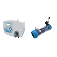
2 Aqua salt
+
description
A salt chlorine generator is a device that produces chlorine to
disinfect pool water through an electrolytic reaction that produces
sodium hypochlorite from an aqueous solution of sodium chloride
(common cooking salt). This way, you will no longer have to buy,
handle or store the common chemicals for pools (sodium
hypochlorite, trichloro, dichloro). You will only have to add a certain
amount of salt, depending on the size of your pool, until reaching a
concentration between 2.00-4.5 g/l ( 2,000-4,500 ppm). After
disinfection, sodium and chlorine will naturally tend to re-join to form
salt. Therefore, the initial dose of sodium chloride is continuously
recycled and reused. Potential loss can be caused by water
additions, reflux or drainage.
General information: chlorine production takes place only if a stabilized water flow goes through the
cell. When this occurs, chlorine generated is directly proportional to the current of the cell, whose
electrodes have a constant potential difference. In its turn, the current depends on the concentration of
salt in the water, and on the disposition of the electrodes. The electrolytic cell works with a series of
cycles of 15 minutes. Each cycle is composed by an alternation of ON/OFF phases whose duration is
proportional to the set chlorine percentage (Internal or External timer mode) or proportional to the
measured value of chlorine or Redox (proportional operating mode). Chlorine generation is periodically
interrupted to switch the electrode polarization, which maintains stable performance and prevents
limescale from depositing on the surface of the electrodes. After a programmable polarization time (from
1 to 16 hours), the “Clean” phase will start. This lasts 10% of the set polarization period. At the end of
this phase, before resuming chlorine generation, the polarity of the electrodes is switched again. The
activation can be done as follows:
• External timer: in this case, the electrolytic cell generates chlorine when it is electrically
supplied. It is sufficient to power the device through a timer of the pool, by a timer (time switch)
or directly via the circulation pump and set the desired percentage of production of chlorine.
Current
density
(mA/sq.
cm)