EasyManua.ls Logo

Aqua SALT+ - Installation Example

Default Icon
51 pages
Print Icon
To Next Page IconTo Next Page
To Previous Page IconTo Previous Page
Loading...
AQUA SALT
+
MAINTENANCE AND INSTRUCTION MANUAL
Salt chlorine genera ENGLISH
ADSP7000753 rev. 5.0 09/07/2019 14/51
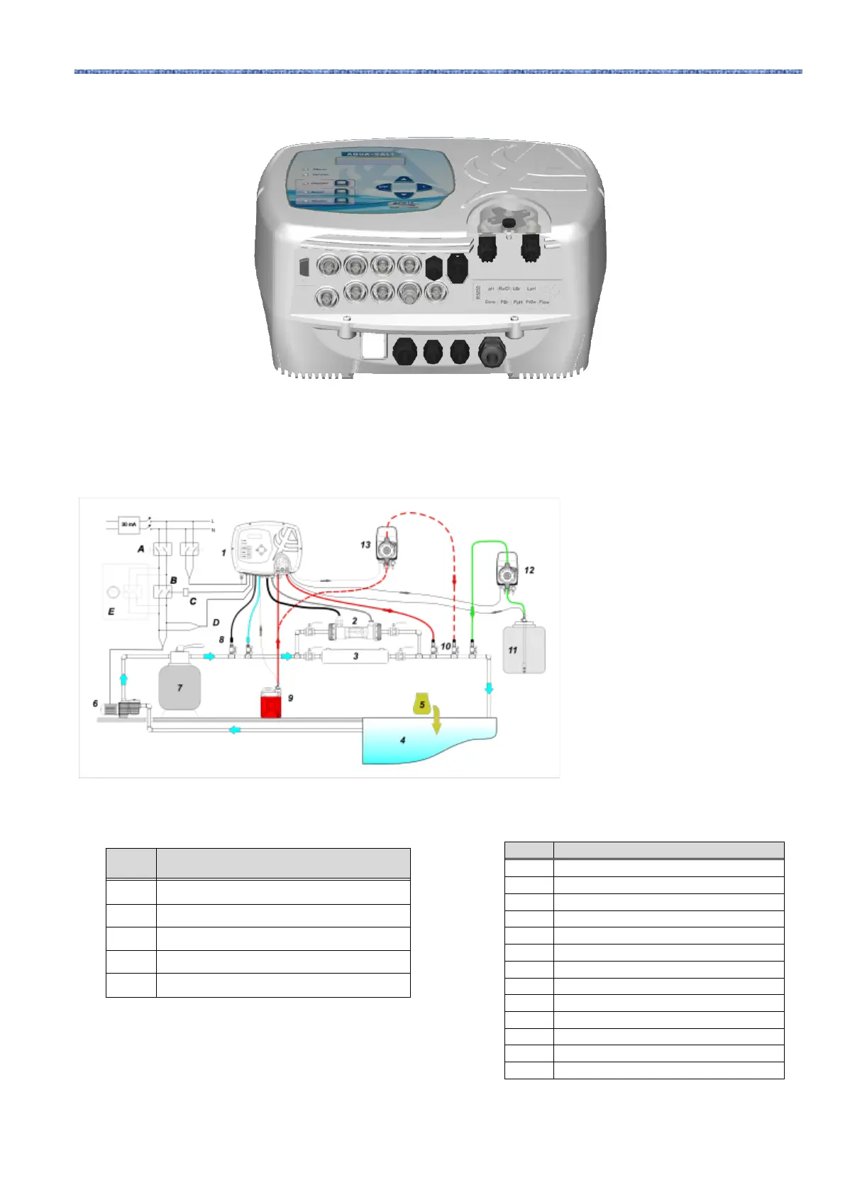
3 Connector overview. Lower part of the control box
3.2.2
Installation
example
The sample installation diagram below refers to the pH, pH/Rx, pH/ClJ models.
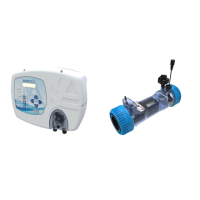
Number 12 in picture 9 indicates the
electromagnetic pump for brine
restoration. In order for the pump to
work correctly, it is necessary to
connect the level signal of the product
in the tank. Connect the pump to the
connector indicated with PBr, and the
level signal to the connector indicated
with LBr, both shown in picture 8.
Number 13 in picture 9 indicates an
external pump to correct pH. If you
want to use the external pH pump,
connect it to the PPh connector, and
connect the level signal to the
connector indicated with LPh, shown
in picture 8.
ID
Description
A
Bipolar switches
B
Contactor to activate the circulation pump
C
Control relay of the contactor
D
Circulation pump operating feedback
E
External auxiliary activation
ID
Description
1
AQUA SALT
+
control system
2
Electrolytic cell
3
Heat exchanger
4
Pool (max. capacity 200 cu. m)
5
Pool salt (NaCl)
6
Recirculation pump
7
Sand filter
8
Probes (pH, Redox)
9
pH corrector tank
10
Injection valves
11
Brine
12
Brine electromagnetic pump
13
pH electromagnetic pump
4. Installation example pH, Rx and ClJ models. It is advisable to enter the redox /
chlorine probe before the sand filter.

Table of Contents

Related product manuals