QUARTZ
TM
SMART VALVE AND DIVERTER
1
To ensure safe operation and installation of this product, the Quartz
TM
smart valve and
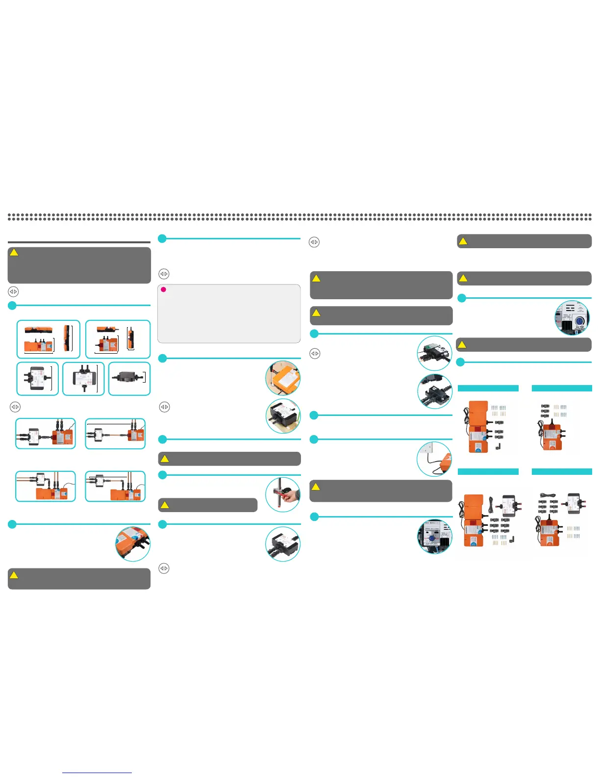
diverter MUST be installed in one of the orientations shown.
PLEASE NOTE: If installing a diverter please also note all areas marked with this symbol.
INSTALLATION
For installation with the diverter.
2
Isolation valves are supplied with the Quartz
TM
smart valve and
diverter valve and must be fitted on both inlets and the blended
water outlet/ outlets. For optimum performance on gravity fed
systems 22mm pipe work should be run as close to the Quartz
TM
smart valve as possible before reducing down to 15mm. All pipe
work should be supported.
The inlet supply centres are 48mm.
Please note arrow on isolation valve to indicate direction of flow.
DO NOT use compression fittings on the inlet and outlet spigots this will aect the
warranty if fitted.
3
Choose the position for your Quartz
TM
smart valve as close to the shower control as possible.
The Quartz
TM
smart valve may be sited in the roof space above the proposed shower site, in the
airing cupboard or behind a screwed bath panel if more convenient. If siting in the roof space,
ensure that freezing cannot occur and that no insulation material is placed under or over the
Q
TM
smart valve or diverter. Please refer to the system layout.
If installing a diverter, choose the position for the Quartz
TM
smart valve as close to the
diverter as possible, within the range of the 2m connecting data cable provided.
4
Place the Quartz
TM
smart valve on a solid mounting surface, and
place the fixing feet into suitable positions. Mark then drill and
prepare suitable fixings before securing the Quartz
TM
smart valve
to the mounting surface using the screws provided, (if suitable).
If installing the diverter this also needs to be installed as per the
above instructions in step 4
5
Flush through both hot and cold supply pipes.
The maximum hot water inlet temperature must be no more than 65˚C.
6
Attach the supply pipes to the Quartz
TM
smart valve, ensuring that
the cold and hot feeds are fitted into the appropriately marked
inlets.
Do not solder near to plastic components.
7
Prepare and connect a pipe from the mixed water outlet on the
Quartz
TM
smart valve through the wall to the proposed siting for
the shower outlet.
Using pipe clips as appropriate, ensure that all pipe work is
perpendicular to the Quartz
TM
smart valve, i.e. not putting any
strain on the fittings.
If installing a diverter prepare and connect the pipe from the mixed water outlet on the Q
TM
smart valve through to the diverter inlet. The diverter can be fitted directly onto to the
Q
TM
smart valve outlet if required on the HP/Combi system installation. A cranked M/F elbow
is supplied for the Gravity Pumped system for ease of installation. Refer to images in point 1.
Ensure the isolation valves are connected to the diverter outlets with the arrows correctly
aligned according to the direction of flow. Using pipe clips as appropriate, ensure that all pipe
work is perpendicular to the Quartz
TM
smart valve and diverter, i.e. not putting any str
ain on the fittings.
Prepare and connect the pipes from the diverter outlets to the proposed siting for the outlets.
To maximise flow rates we recommend using copper pipe with the minimum amount of
elbows on all pipes leading to and from the Quartz
TM
smart valve.
Ensure the pipe work connections have been flushed through.
If fitting a bath outlet, a suitable non restrictive double check valve (not supplied) MUST be
fitted to the blended outlet pipe in line with the current water regulations.
BEFORE ANY ELECTRICAL ADJUSTMENT IS ATTEMPTED, THE ELECTRICITY SUPPLY MUST BE
TURNED OFF AT THE MAINS SWITCH.
ELECTRICAL INSTALLATION MAY ONLY BE CARRIED OUT BY A QUALIFIED PERSON.
8
Unscrew the single fixing on top of the Quartz
TM
smart valve and
carefully tilt the lid up and o the location lugs and pull the lid clear.
If installing the diverter also remove the lid following the
instructions above in step 8.
9
As installation diers for dierent controls please refer to the relevant smart controller
installation guide for the Quartz
TM
smart valve and diverter wiring.
10
Connect the Quartz
TM
smart valve power lead to a double pole 3
amp fuse switched spur incorporated in the fixed wiring circuit, in
accordance with current wiring rules. Ensure that this is located
in an accessible, dry location and not in the bathroom.
THIS APPLIANCE MUST BE EARTHED
We recommend protecting surface mounted cables in suitable approved conduit to avoid the risk of
damage from vermin.
The power lead should also be clipped in place with ‘P’ clips or similar to avoid accidents.
11
The Q
TM
smart valves are supplied factory set with the flow rate at
either ‘NORMAL HP’ or ‘NORMAL GRAVITY’ mode depending on
which system has been ordered.
BALANCED HP SYSTEMS:
Standard Q
TM
smart valves fitted to balanced high pressure sys-
tems may be set to ‘NORMAL HP’ or for water economy ‘ECO’
modes.
STANDARD COMBINATION BOILER SYSTEMS:
For Standard Quartz
TM
smart valves installed on combi boiler
systems, for optimum performance we recommend setting to the
‘COMBI’ mode.
The ‘ECO’ flow rate mode should NOT be selected for shower or bath systems fitted
to combination boilers.
PUMPED QUARTZ
TM
SMART VALVE:
Pumped Quartz
TM
smart valves are fitted to gravity systems may be set to ‘NORMAL
GRAVITY’ or for water economy ‘ECO’ modes.
When making any adjustment to the Quartz
TM
smart valve settings the power must
be isolated.
12
Run the shower at maximum temperature (factory pre set to
45ºC). If required, maximum temperature adjustment can be
made with a flat bladed screwdriver using the ‘MAX TEMP
ADJUSTMENT’ control as indicated. When the temperature
has been set to the desired position, carefully replace the
Quartz
TM
smart valve lid and secure the fixing screw, hand
tight only.
Site conditions can aect temperature settings, installer to adjust as required.
All copper pipe work must be cross-bonded and connected to a reliable earthing point.
13
Please refer to the separate Q
TM
controller installation guide to complete installation.
Quartz
TM
smart valve connected
directly to diverter valve
Quartz
TM
smart valve connected to
diverter with additional pipe
Quartz
TM
smart valve connected
directly to diverter valve
Quartz
TM
smart valve connected
to diverter with additional pipe
HP/Combi Quartz
TM
smart valve
Gravity pumped Quartz
TM
smart valve
This product must be installed by a competent person in accordance with the relevant
current Water Supply Regulations.
In addition to the guide below it is essential that the written instructions overleaf are read
and understood and that you have all the necessary components (shown bottom right)
before commencing installation.
The Quartz
TM
smart valves are supplied with universal fixings intended to secure it to a
solid mounting surface.
The Quartz
TM
smart valve and diverter must be sited in a position that is safely accesible
for servicing and commissioning purposes. When fitted in the loft space, the route to and
the area around the Quartz
TM
smart valve must be boarded to ensure a safe working
environment.
The optimum position for the Quartz
TM
smart valve and diverter is in the roof space above
the Q
TM
controller site to take full advantage of the ease and speed of installation.
The distance between the Quartz
TM
smart valve and main Q
TM
controller must be within the
range of the 10m data cable supplied.
The diverter inlet has been designed to enable connection directly inline with the HP/
Combi Quartz
TM
smart valve outlet isolation valve connection or o the Gravity Pumped
Quartz
TM
smart valve outlet using the cranked M/F elbow connection fitting.
)
. .
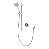
Single outlet
Components (Gravity pumped) Components (HP/Combi)
Components (Gravity pumped) Components (HP/Combi)
Single outlet
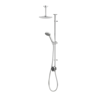
With diverter
With diverter
265mm
70mm
350mm
270mm
445mm
445mm
270mm
Max 2m
Max 2m
197mm
240mm
70mm
 Loading...