)
. .
Helpful tip...
AQUALISA Q
TM
In addition to the guide below it is essential that the Important information
section is read and understood and that you have all the necessary
components before commencing installation. Failure to install the product in
accordance with these instructions may adversely aect the warranty terms
and conditions. Do not undertake any part of this installation unless you are
competent to do so. Prior to starting, ensure that you are familiar with the
necessary plumbing regulations required to install the product correctly and
safely.
1
Install Quartz
TM
smart valve and diverter box (if applicable) following the
separate installation guide.
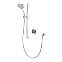
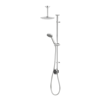
2
Locate a suitable entry point in the ceiling or coving for the riser rail, avoiding
joists and services. Position the rail assembly against bathroom wall in desired
position and mark centre of rail on ceiling/coving.
The centre of the riser rail stands 45mm from the wall.
3
Drill a hole in the ceiling/coving that is a minimum Ø30mm maximum Ø40mm.
If coved ceiling remove the ceiling cover plate from the riser rail.
8 9
4
Ax the paper template to the wall in the desired location ensuring the shower
controller is at a suitable height.
5
Mark the fixing points as indicated on the template.
Helpful tip...
Prior to drilling the fixing holes oer the assembly into position and check
the following points:
The chrome riser rail is positioned within the drilled ceiling hole,
(no copper pipe visible in the shower area).
There is adequate working clearance above the top of the rail in the
roof space.
The controller is at a suitable height for all family members.
Location of the top bracket does not interfere with the maximum usage
height of the PINCH GRIP
TM
.
)
. .
Use a spirit level where indicated on the paper template to ensure your
template is square.
6
Drill the fixing points as previously marked using a suitable 6mm drill bit and fit
the supplied wall plugs (if suitable).
7
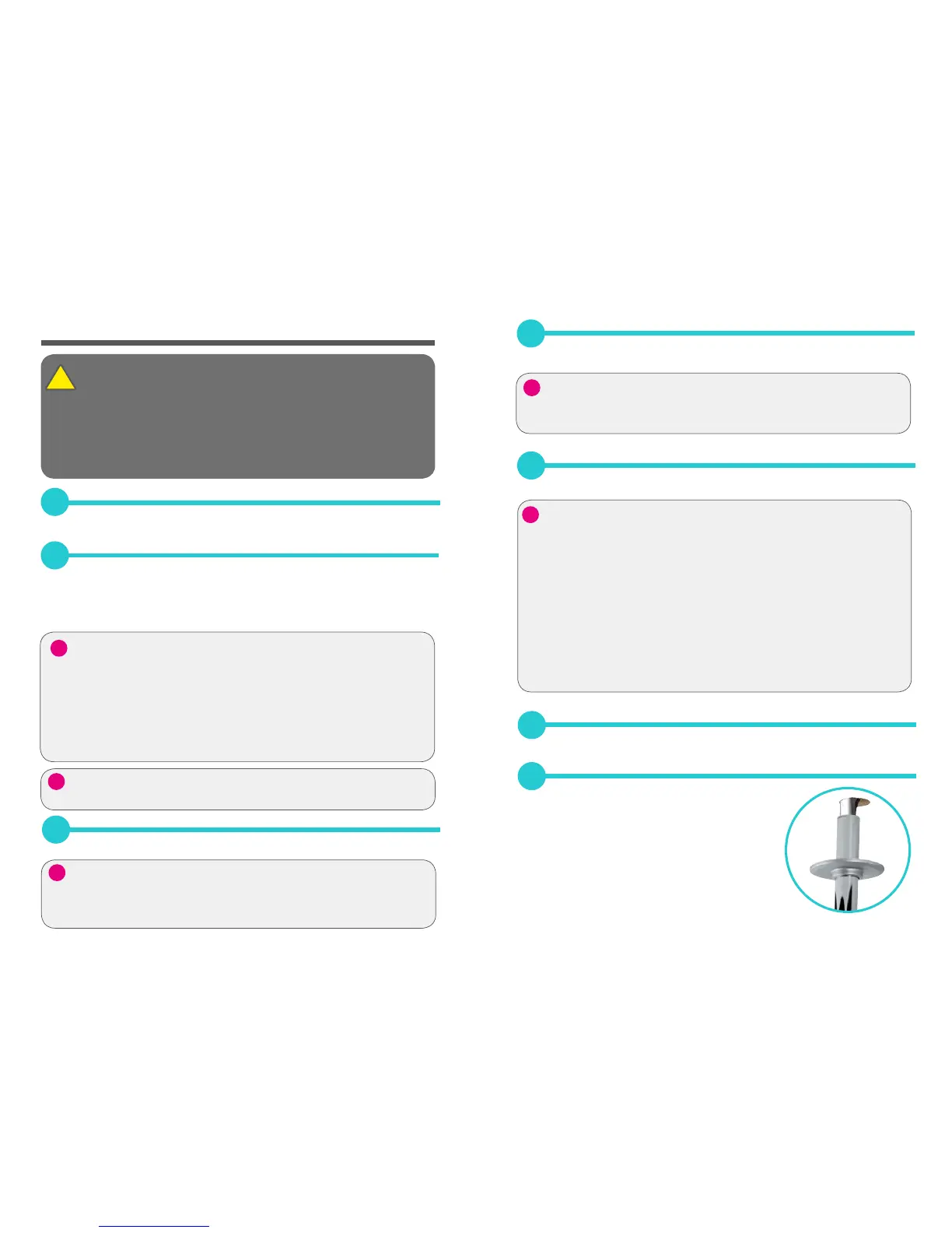
Feed the data cable followed by the rail assembly
containing the supply pipe through the hole in
the ceiling.
INSTALLATION
)
. .
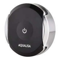
Helpful tip...
Positioning the Q
TM
controller
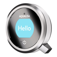
The Q
TM
controller is activated by a proximity sensor on the front of the
Q
TM
controller. This sensor detects motion from up to 0.5m, directly in
front of the device. It is therefore important that the device is positioned
so that it will detect the user approaching and moving away from the
shower at 0.5m.
The position should also be taken into consideration when utilising the
Water Save mode, refer to point 63.
)
. .
If the ceiling height is over 2.4m (8ft) a riser rail extension kit will be
required. Contact our Customer Service department to purchase a 550mm
riser rail extension kit, (Part No. 910596).
)
. .
Helpful tip...
 Loading...