Revision Date – 22/12/2014 page 41
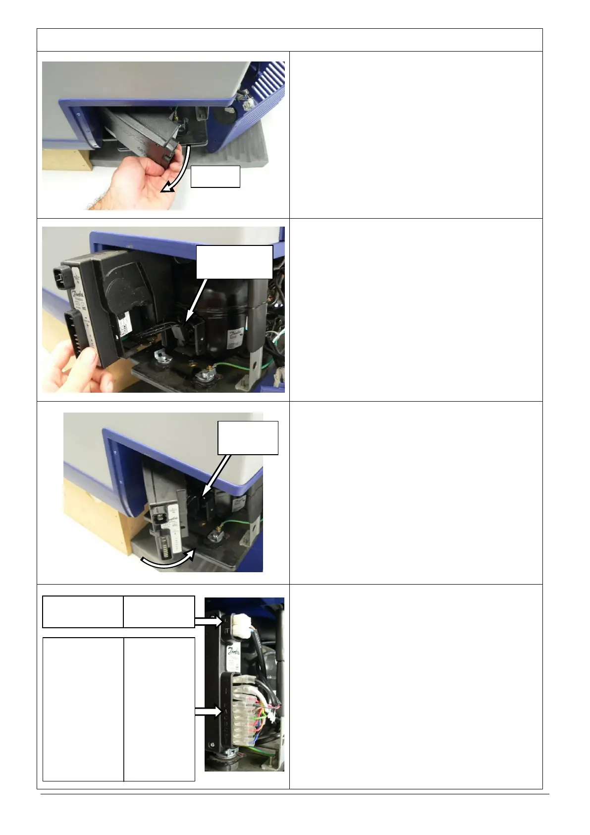
Remove the compressor control unit by rotating it
away from the body of the fridge as shown.
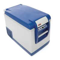
Disconnect the 3 wire plug that connects the
compressor control unit to the compressor.
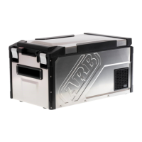
Connect the 3 wire plug from the new control unit
to the compressor.
Fit new control unit to the compressor and attach
using 1 Phillips head screw.
HINT: When fitting control unit, locate back
edge of unit on bracket and then rotate
towards body of fridge as shown.
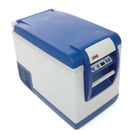
Connect the 11 connectors to the new control unit
in the correct order (refer to diagram for wiring
details).
Reposition compressor mounting base and fasten
using the original 6 screws (35L and 47L only).
Refit the rear cover.
Restore power to fridge and check for correct
operation.
CAUTION: Ensure that all cables are securely
fastened away from sharp, moving
or hot surfaces.
‘L’ – BROWN (AC Socket)
‘N’ – BLUE (AC Socket)
‘-’ – BLACK (DC Socket)
‘+’ – WHITE (DC socket)
– YELLOW (lower PCB)
– RED (Fan)
‘F’ – BLACK (Fan)
‘A’ – BROWN (lower PCB)
‘C’ – GREEN (lower PCB)
‘D’ – RED (lower PCB)
‘C’ – ORANGE (lower PCB)
‘P’ – BLACK (lower PCB)
‘T’– BLUE (lower PCB)