Revision Date – 22/12/2014 page 42
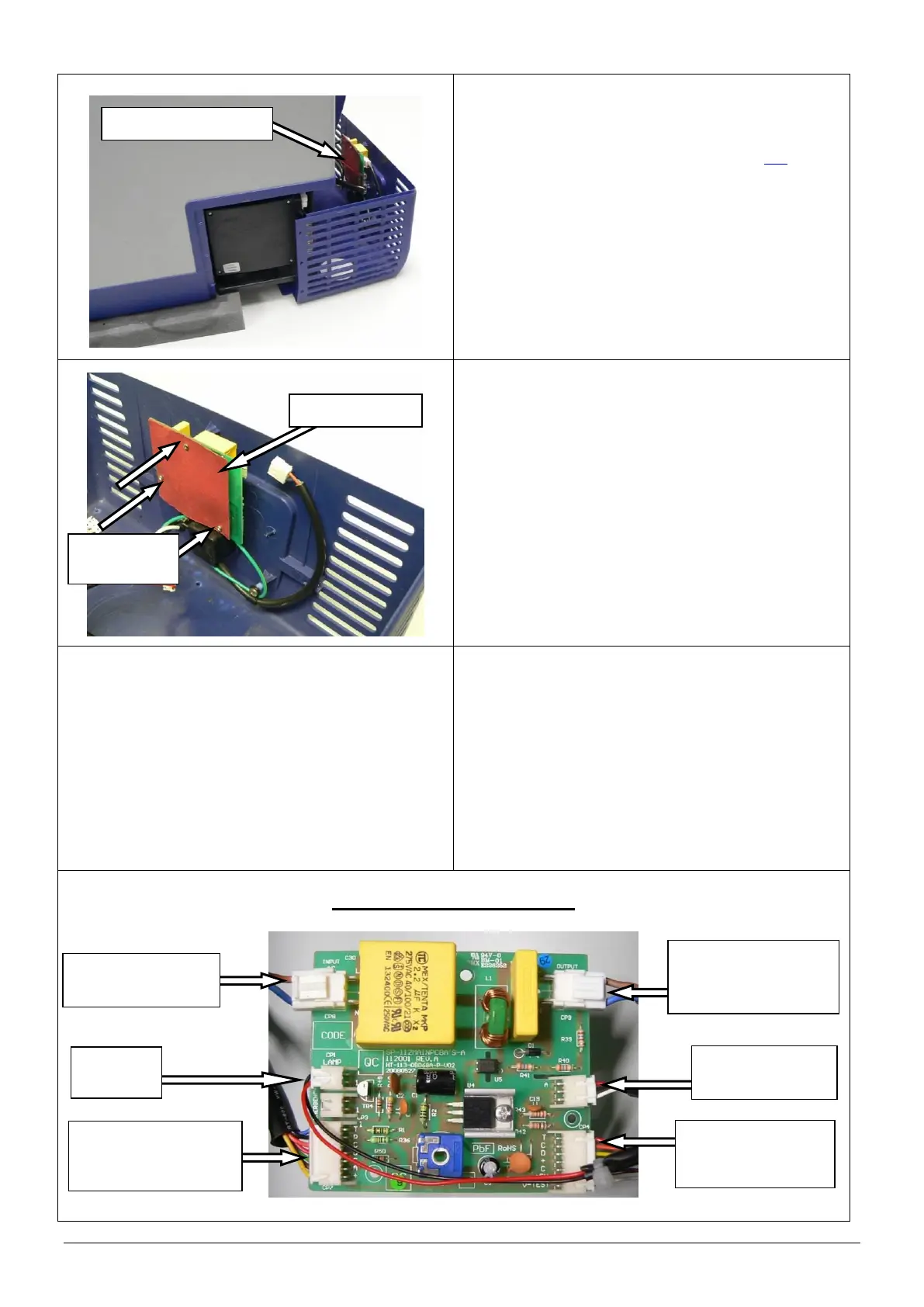
9.4 Main circuit board - Replace
Disconnect all power leads from the back of the
fridge.
Remove the rear cover (refer to section 9.2).
Locate the main circuit board and disconnect all 6
connectors.
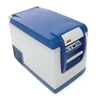
NOTE: The main circuit board and corresponding
connectors were changed in January
2014. Refer to the following steps for
correct wiring for each PCB.
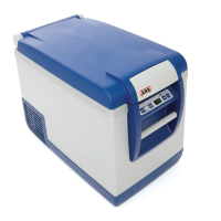
Mark the location of each connector before
disconnecting.
Remove the 3 screws that connect the main
circuit board to the rear cover.
Remove the main circuit board.
Replace the main circuit board and reconnect
using the original 3 screws. Do not over tighten
the screws.
NOTE: Ensure that the backing card is refitted.
Reconnect the 6 electrical connectors.
Refit the rear cover.
Restore power to the fridge and test to confirm
correct operation.
CAUTION: Ensure that all cables are securely
fastened away from sharp, moving
or hot surfaces.
MAIN PCB – pre January 2014
‘DISPLAY’
To control panel
circuit board
‘OUTPUT’
To compressor
control unit
‘COMP’
From compressor
control unit