Fitting instructions# 3789528
Copyright © 2005 by ARB Corporation Limited. All rights reserved, this document must not be reproduced without the express authority of ARB Corporation Ltd
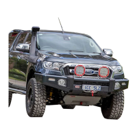
165. Fit the 35mm wide spacer and the M12 x
1.75 x 80 bolt, M12 washer and M12 spring
washer. Leave loose at this stage.
166. Repeat for LH side.
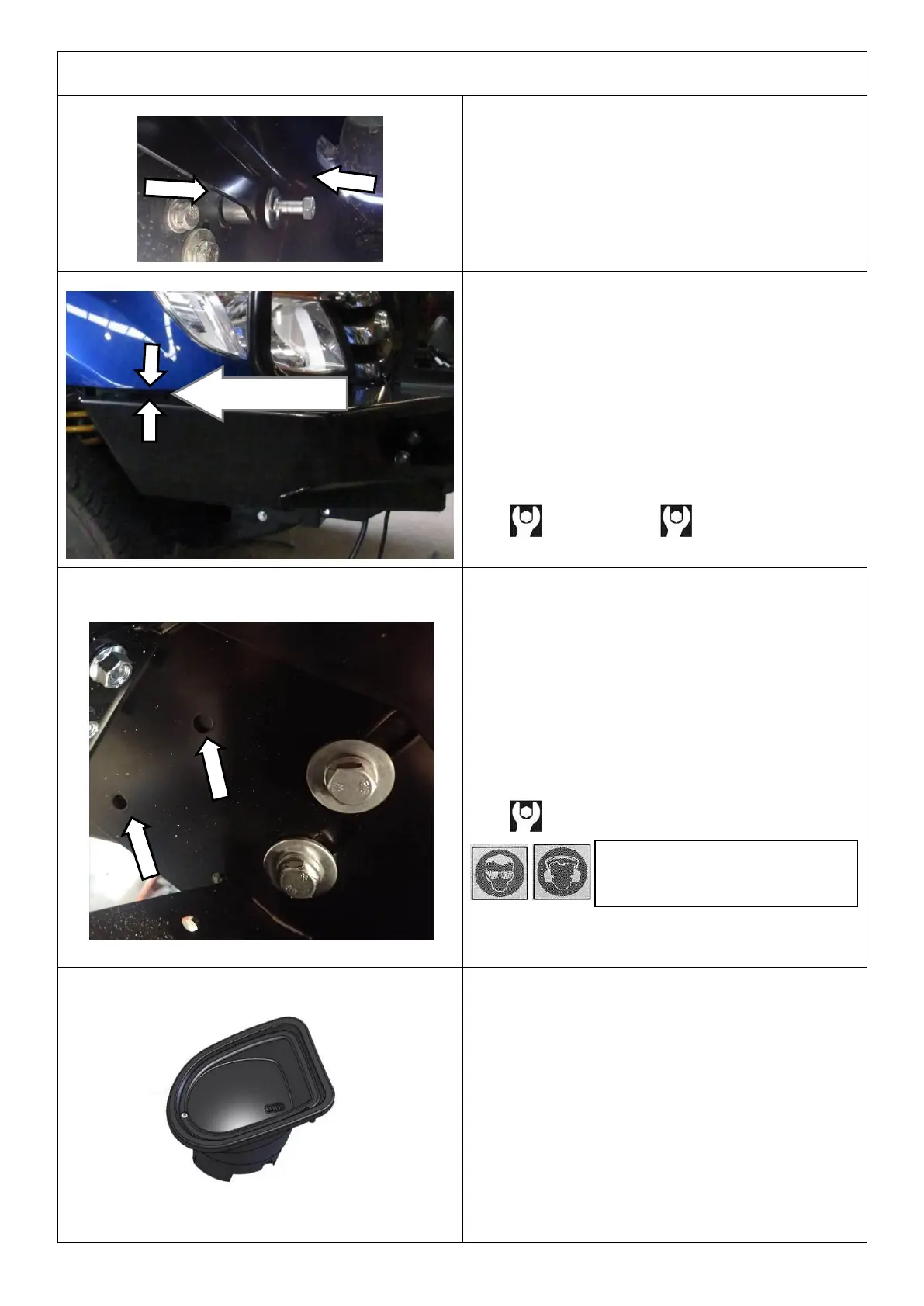
167. Centralise the bar and tighten all mounting
bracket related fasteners to the specified
torque.
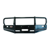
168. Position the bar so that it is level and there is
a gap between the top face of the wings and
the bottom edge of the guards of 18-22mm
and the wing tips are aligned with the edge of
the wheel arch.
169. Tighten all remaining fasteners to the
specified torques for M10 and M12 sizes.
M10 - 44 Nm. M12 - 77 Nm.
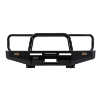
170. Double check the position of the bar.
171. When happy with the position of the bar drill
2 x Ø10mm pinning holes using the pre-cut
holes in the bar uprights as guides.
172. Use paint or rust protection on the drilled
holes.
173. Pin the holes using 2 x M10 x 30 SEMS bolts
and 2 x M10 flange nuts.
174. Repeat for LH side.
M10 - 44 Nm.
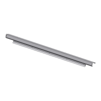
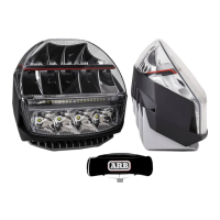
175. Assemble and install combination light
surrounds (P/N 3500530) as per instructions
no. 3789190 supplied with surround kit. Note:
Optional fog lamps can be installed at this
point as per fitting instruction supplied with
fog lamp kit no. 3500640.
176. Connect indicator loom and reconnect
parking sensor loom, secure cabling.
Check the operation of parking sensors and
all lights wired.
CAUTION: Cable-tie all cables together and
keep all cables clear of sharp edges and all
moving parts.
Warning: Drilling operations
can result in flying metal debris,
safety glasses should be worn.