Operation Guide P341/EN O/B11
Commissioning and CHAPTER 3
Maintenance Page 27/80
MiCOM P341
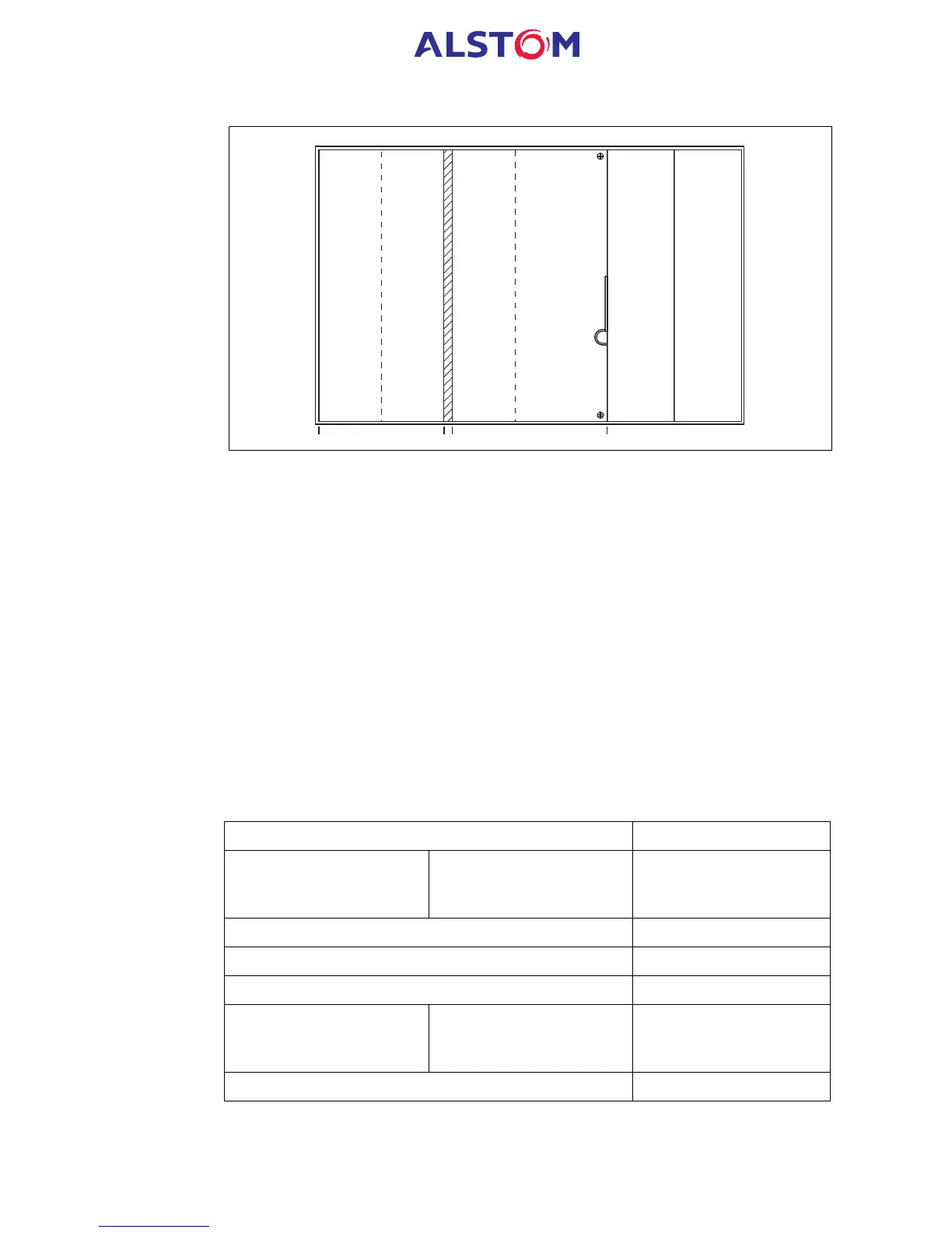
12 3 4 5 6
Power supply
board
Relay board Input board Transformer board Not used IRIG-B board
Power supply module
Input module
Figure 4: P341 PCB/module locations (viewed from front)
The PCBs within the relay are now accessible. Figure 4 shows the PCB locations for
the relays in size 40TE cases.
Note: The numbers above the case outline identify the guide slot reference for
each printed circuit board. Each printed circuit board has a label stating the
corresponding guide slot number to ensure correct re-location after removal.
To serve as a reminder of the slot numbering there is a label on the rear of
the front panel metallic screen.
The 64-way ribbon cable to the front panel also provides the electrical connections
between PCBs with the connections being via IDC connectors.
The slots inside the case to hold the PCBs securely in place each correspond to a rear
terminal block. Looking from the front of the relay these terminal blocks are labelled
from right to left.
Note: To ensure compatibility, always replace a faulty PCB with one of an identical
part number. Table 14 lists the part numbers of each PCB type.
PCB Part Number
Power supply board
(24 – 48V dc)
(48 – 125V dc)
(110 – 250V dc)
ZN0001 001
ZN0001 002
ZN0001 003
Relay board ZN0002 001
Input board ZN0005 001
Opto board ZN0005 002
IRIG-B board
(IRIG-B input only)
(Fibre optic port only)
(Both)
ZN0007 001
ZN0007 002
ZN0007 003
RTD board ZN0010 001
Table 14: PCB part numbers



 To Next Page