P341/EN O/B11 Operation Guide
CHAPTER 3 Commissioning and
Page 28/80 Maintenance
MiCOM P341
8.3.2.1 Replacement of the main processor board
The main processor board is located in the front panel, not within the case as with all
the other PCBs.
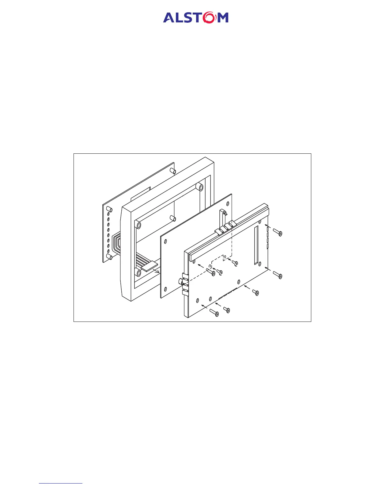
Place the front panel with the user interface face-down and remove the six screws
from the metallic screen, as shown in Figure 5. Remove the metal plate.
There are two further screws, one each side of the rear of the battery compartment
recess, that hold the main processor PCB in position. Remove these screws.
The user interface keypad is connected to the main processor board via a flex-strip
ribbon cable. Carefully disconnect the ribbon cable at the PCB-mounted connector
as it could easily be damaged by excessive twisting.
Figure 5: Front panel assembly
The front panel can then be re-assembled with a replacement PCB using the reverse
procedure. Ensure that the ribbon cable is reconnected to the main processor board
and all eight screws are re-fitted.
Refit the front panel using the reverse procedure to that given in section 8.3.2. After
refitting and closing the access covers on size 60TE cases, press at the location of the
hinge-assistance T-pieces so that they click back into the front panel moulding.
After replacement of the main processor board, all the settings required for the
application will need to be re-entered. Therefore, it is useful if an electronic copy of
the application-specific settings is available on disk. Although this is not essential, it
can reduce the time taken to re-enter the settings and hence the time the protection is
out of service.
Once the relay has been reassembled after repair, it should be recommissioned in
accordance with the instructions in sections 1 to 7 inclusive of this chapter.



 To Next Page