36
SECTION 7
MAINTENANCE INFORMATION
a Vice-Grip 10CR or similar plier as illustrated in Figure
7-14 and remove the drive chain.
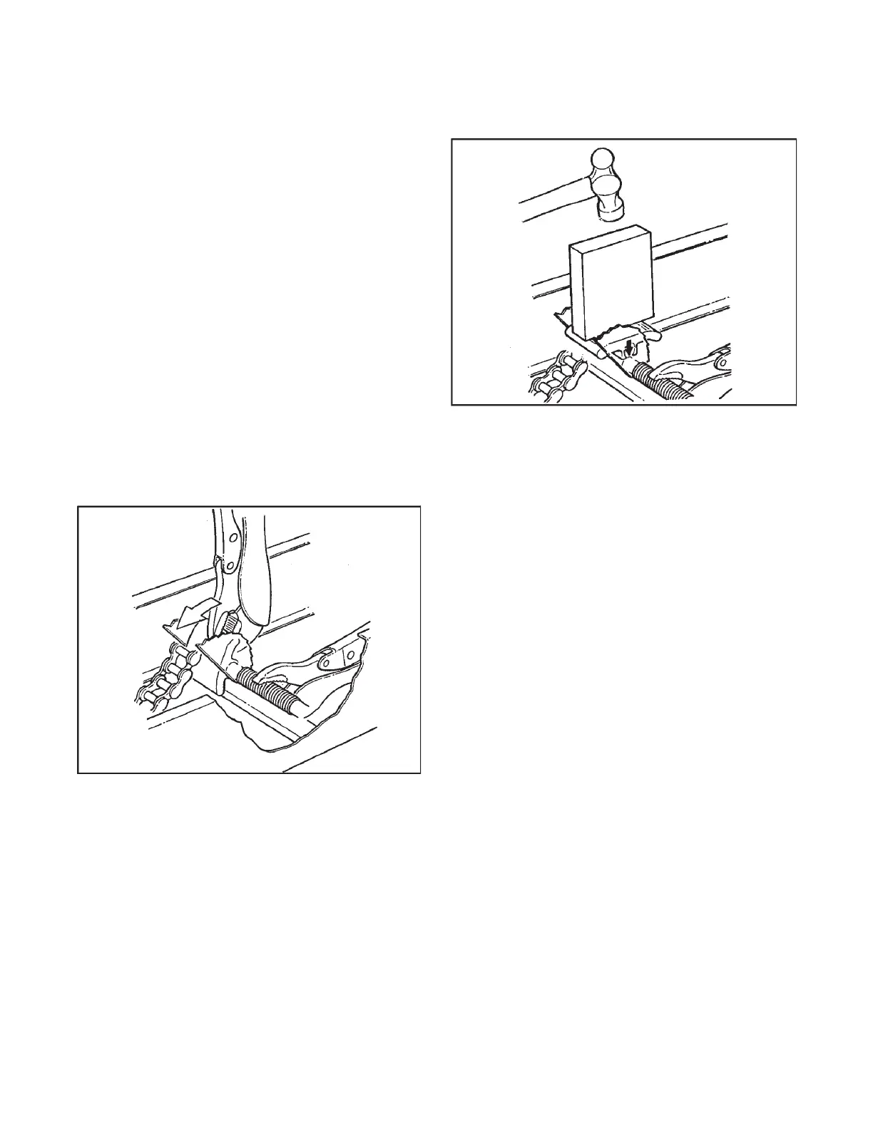
3. Withpliers,prythesliderblockothecamassemblyas
illustrated in Figure 7-14.
4. Place a new slider block over the shaft of the cam assem-
bly.
5. Using a piece of wood (or similar material) pressed against
the top of the slider block, carefully hammer the piece of
wood so the slider block snaps onto the cam assembly shaft
as shown in Figure 7-15.
6. Re-install the drive chain and remove the locking pliers
securing the cam assembly in its lowest position.
7. Pull up on the cam assembly to allow it to take up as much
chain slack as possible.
8. Replacetheoorpans.
Figure 7-14. Prying the Slider Block o the Cam Assembly.
Figure 7-15. Hammering Slider Block into place.
7.2.5 TIRE INFLATION (without track system)
Improperlyinatedtirescancausethevehicletopulltoone
side,requiringconstantsteeringcorrection.Suggestedina-
tion is based on the type of rim in the wheel, and are listed
below.
Standard 8" Steel Rim 2.5 to 3.5 psi
(17 to 24 kPa)
Standard 9" Steel Rim 2.5 to 3.5 psi
(17 to 24 kPa)
Oset9"SteelRim 2.5to3.5psi
(17 to 24 kPa)
Oset9"AluminiumBeadlock 1.5to3.5psi
(10 to 24 kPa)
Oset9"SteelBeadlockRim 1.5to3.5psi
(10 to 24 kPa)
The maximum operating pressure for all tires is 7.0 psi (48
kPa).
A special low pressure tire gauge (ARGO Part No. 619-10) is
available from your ARGO dealer.
CHANGING TIRE PRESSURE FOR DIFFERENT
TERRAIN CONDITIONS
Thetirepressureshouldbeadjustedaccordingtodierences
in terrain. Observance of these guidelines will lead to less wear
& tear on both vehicle and tires. The operator should equip
the vehicle with a low pressure tire gauge (Part No. 619-10)
and with a hand pump.