38
SECTION 7
MAINTENANCE INFORMATION
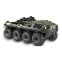
Ensure the tire bead is seated properly into the rim lip around
the entire perimeter of the rim (see Figure 7-19), before
placing the rim ring into position to the top of the tire bead.
Align machined edges of rim ring with machined edges of
rim. Figure 7-19.
Figure 7-19 Align rim ring with rim.
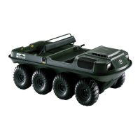
Install (10) fasteners to all locations around tire/rim assembly
and torque to 7.2 ft.lbs (10 Nm). Torque in a cross pattern
sequence. Do NOT over-torque. Figure 7-20.
Figure 7-20 Install fasteners.
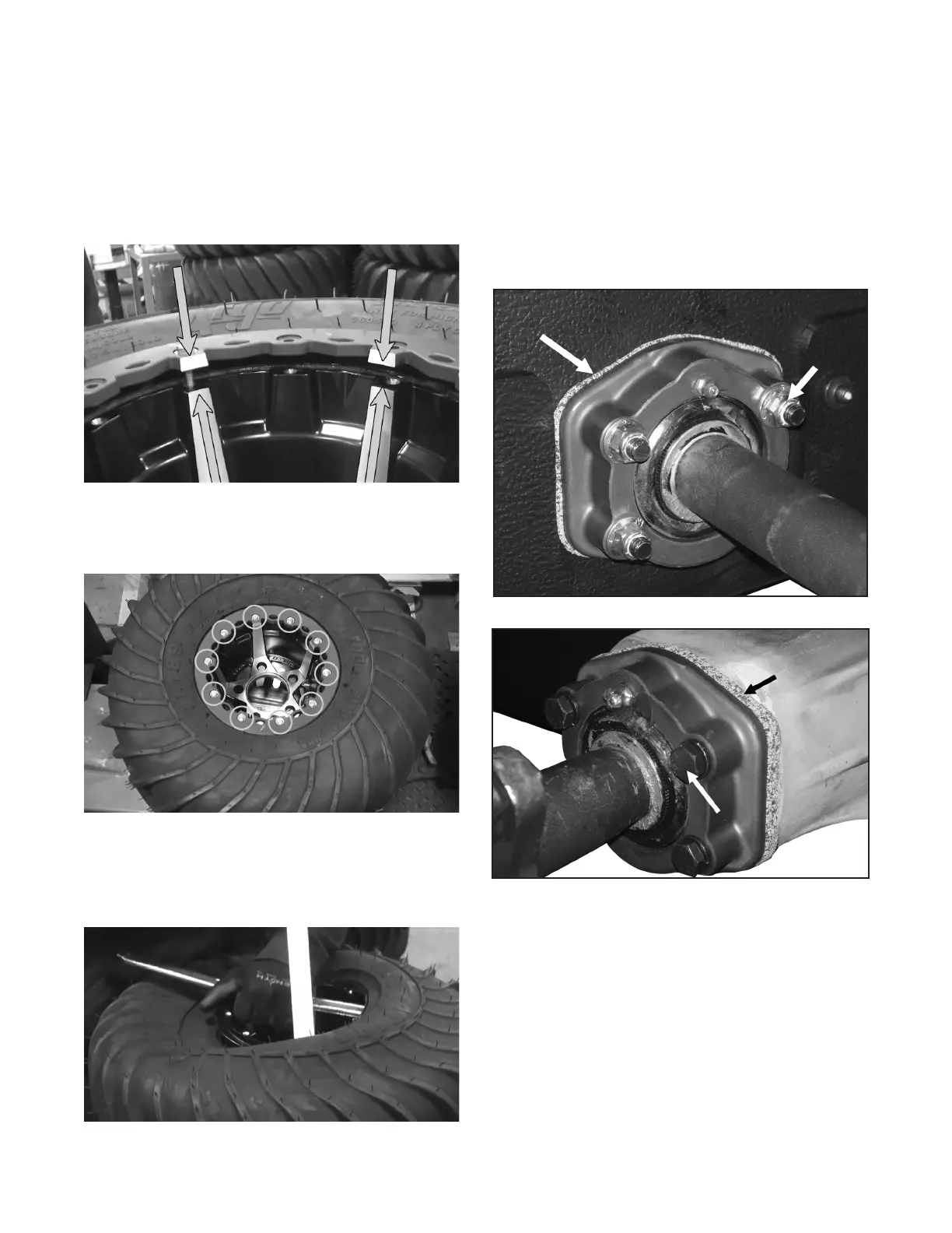
Turn rim over and spoon tire onto lip of opposite side. Figure
7-21. Place second rim ring into position as described in previ-
ous steps and install fasteners. Torque to 7.2 ft.lbs. (10Nm).
Fillto10psiandcheckforleaks.Setnalairpressureto
1.5 - 2.0 psi.
Figure 7-21
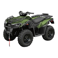
7.2.7 AXLE BEARING MOUNTING
The axles are mounted to your Aurora using special cork
gasketsbetweentheangedbearingsandtheoutsidesurface
of the lower body (see Figure 7-22). During the initial run-
in period, the gasket material may relax causing the nuts to
loosen slightly. These should be checked and re-tightened
after initial 10 hours of use and then after every 100 hours.
See Figure 7-16.
Figure 7-22. Re-tightening bolts (mid axles).
Figure 7-22. Re-tightening bolts (front/rear axles).
7.3 HYDRAULIC BRAKES
7.3.1 GENERAL
Although the hydraulic brake system is self adjusting, the
following require periodic attention:
7.3.2 BRAKE FLUID LEVEL
Afterevery50hoursofoperation,checkthebrakeuidlevel
by removing the master cylinder covers.