!
!
3 Connectors
!
!
3.1 !
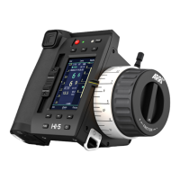
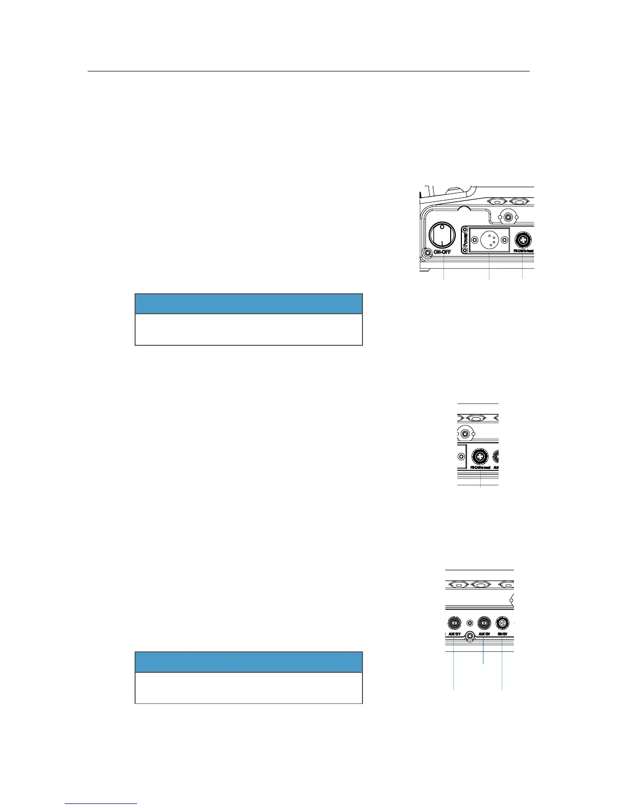
Powering the SRH-3 Control Panel!
!
You can use any 14.4 Volt min. 30W power supply!
or 14.4 Volt battery to power the SRH-3 Control Panel.!
!
Any 4pin XLR conformed power cable can be used.!
!
When using the ARRI SRH-3 Power Supply, the control
panel will be powered through the FS-CAN Bus connector.!
!
NOTE
If the Remote Head does not react to the control panel, !
when the main power switch is on check that the !
SHUT OFF Switch is pulled out.
!
!
!
!
!
!
!
!
3.2 !
Hardwiring the SRH-3 Stabilized Remote Head!
!
The SRH-3 can be hardwired with the Remote Panel using !
the FS-CAN BUS connector.!
!
NOTE
Maximum cable length is 250 meter / 820 feet.
!
!
!
!
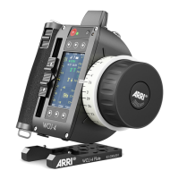
3.3 !
Powering Monitors and Accessories!
!
The SRH-3 Control Panel offers one ARRI RS and two !
Lemo 0B 2pin power out sockets.!
!
NOTE
The ARRI RS does not support the !
classic camera On/Off trigger signal.!
!
!
!
!
!
!
!
 Loading...