6-22 CHP Max™ Headend Optics Platform Chassis, Controllers and Power Supplies 1508685 Rev D
b. Push and remove the seven push pins securing the front left plastic cover to
the circuit card from the left side of the module.
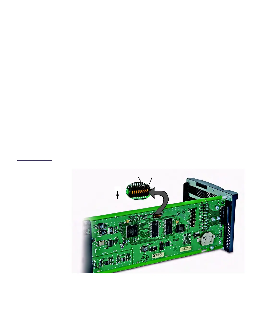
c. Referring to Figure 6.14, set DIP switch #1 to the ON position to force the SMM
to use the default SMM IP address of 192.168.1.1.
d. Reinsert the SMM into the chassis. The latch on the front panel locks when the
module is fully seated. The SMM will now be configured to the default
address.
e. Telnet to the default IP address to reconfigure the correct address and save to
flash memory. Refer to Step 8.
f. Press upward on the latch release on the front panel and slide the module out
the front of the chassis.
g. Set DIP switch #1 to the OFF position.
h. Position the plastic cover so the cutouts in the cover align with the jumpers
on the circuit card and install the seven push pins from the right side to secure
the cover to the circuit card.
i. Reinsert the SMM into the chassis. The latch on the front panel locks when the
module is fully seated. The SMM will now read the configured IP address from
flash memory.
15. Reconfigure your PC’s IP address back to its original IP address.
Figure 6.14
Location of DIP
Switch #1 on SMM
(cover removed)
#1 (IP Address)
ON
DIP Switch
#2 (Password)