24 |Installation Aruba S2500 Series Mobility Access Switch | Installation Guide
5. Leave a minimum of four inches (10cm) of space on the left and right side of the unit for proper air flow
and ventilation.
6. Leave additional space in front and back of the unit to access power cords, network cables, LCD panel,
and LED status indicators.
Rack Mount Installation- Mid
An optional accessory kit is available that allows you mount the S2500 in a standard 19” Telco rack from the
middle of the device.
Required Tools and Equipment
The following tools and equipment are required for installation of an Aruba S2500 mobility access switch:
Mid-Mount Bracket (x2, not used for tabletop installation)
M4 x 8mm Phillips Flat Head Screws (8x, included with rack mount brackets)
M6 x 15mm Phillips Pan Head Screws (4x, 19-inch (48.26 cm) rack system mount screws).
Suitable Screwdrivers for both screw types.
Installation Steps
To install an Aruba S2500 mobility access switch into a two-point 19-inch (48.26 cm) rack system:
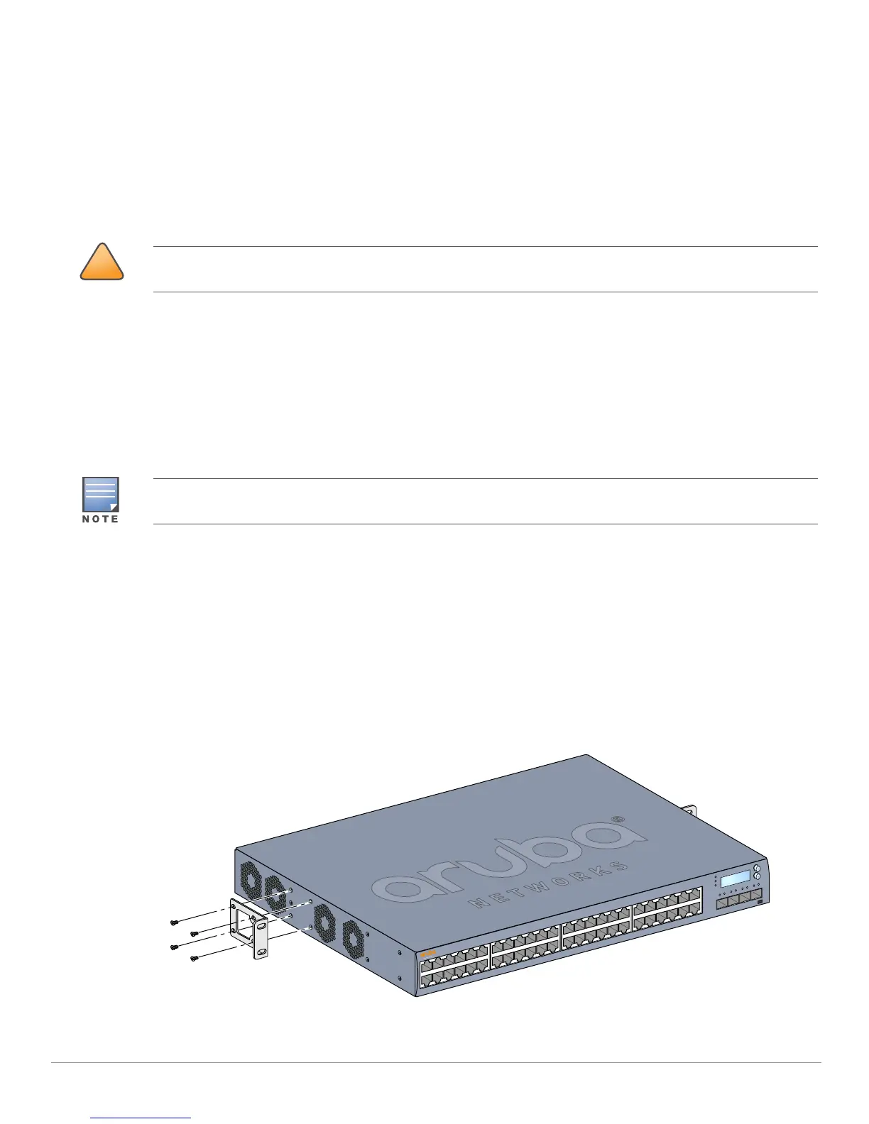
1. Place a rack mount bracket over the mounting holes on one side of the mobility access switch (see
Figure 11).
2. Secure the bracket to the mobility access switch using four M4 x 8mm phillips flat head screws and a
suitable screwdriver.
3. Repeat these steps on the opposite side of the mobility access switch.
Figure 11 Mid-Mount Brackets
Each S2500 should have its own mounting equipment. Do not place other networking equipment directly on top a
mounted S2500. Failure to do so can result in damage to the device.
Some racks require screws that differ from those included with the S2500. Confirm that you have the correct
screws before installing your S2500.