TD 92679GB
12 April 2011 Ver. D
Installation Guide
Elise3
10
4 Installation and Configuration
The Elise3 can be mounted vertically on a wall or be placed horizontally in a 19" rack. It
must be fixed by screws or other fixtures to the wall or rack, and must not be easily
movable.
4.1 Installation Procedure
1 Mount the device, see 4.2 Mounting below.
2 Connect the supply voltage, see 4.3 Supply Voltage on page 14.
3 Access the module via the web interface, see 4.5 Accessing Elise3 on page 17.
4 Fill in all required data, see 4.6 Basic Configuration on page 21.
5 Connect to required equipment, such as Ascom systems, other external equipment,
etc. see
4.4 Connections on page 15.
4.2 Mounting
Elise3 should be placed in a dry environment with a temperature range of 0 to +40ºC.
4.2.1 Wall Mounting
Note: Four screws size 3,5×40 together with four wall plugs and four screws size M3×6,
are delivered with the product. The M3×6 screws are used for attaching the assembly
brackets to the module. Use the 3,5×40 screws for walls made of wood. For walls made of
concrete and bricks use them together with the wall plugs. For other types of walls use
suitable screws and plugs according to wall material.
IMPORTANT: When mounted on a wall, it is of great importance that the connections
are located in a vertical plane to fulfil the fire classification.
1 Fasten the supplied assembly brackets on the bottom side of the module.
2 Use the supplied screws and wall plugs (or other suitable screws and plugs
dependent on wall material) and mount the module as shown in the picture below.
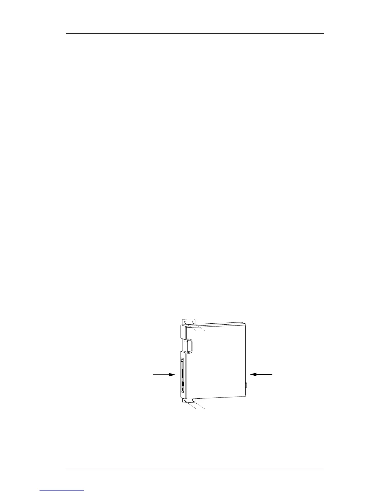
Figure 4. Mounting on a wall
Figure 4.
Connectors
Connectors