TD 92679GB
12 April 2011 Ver. D
Installation Guide
Elise3
16
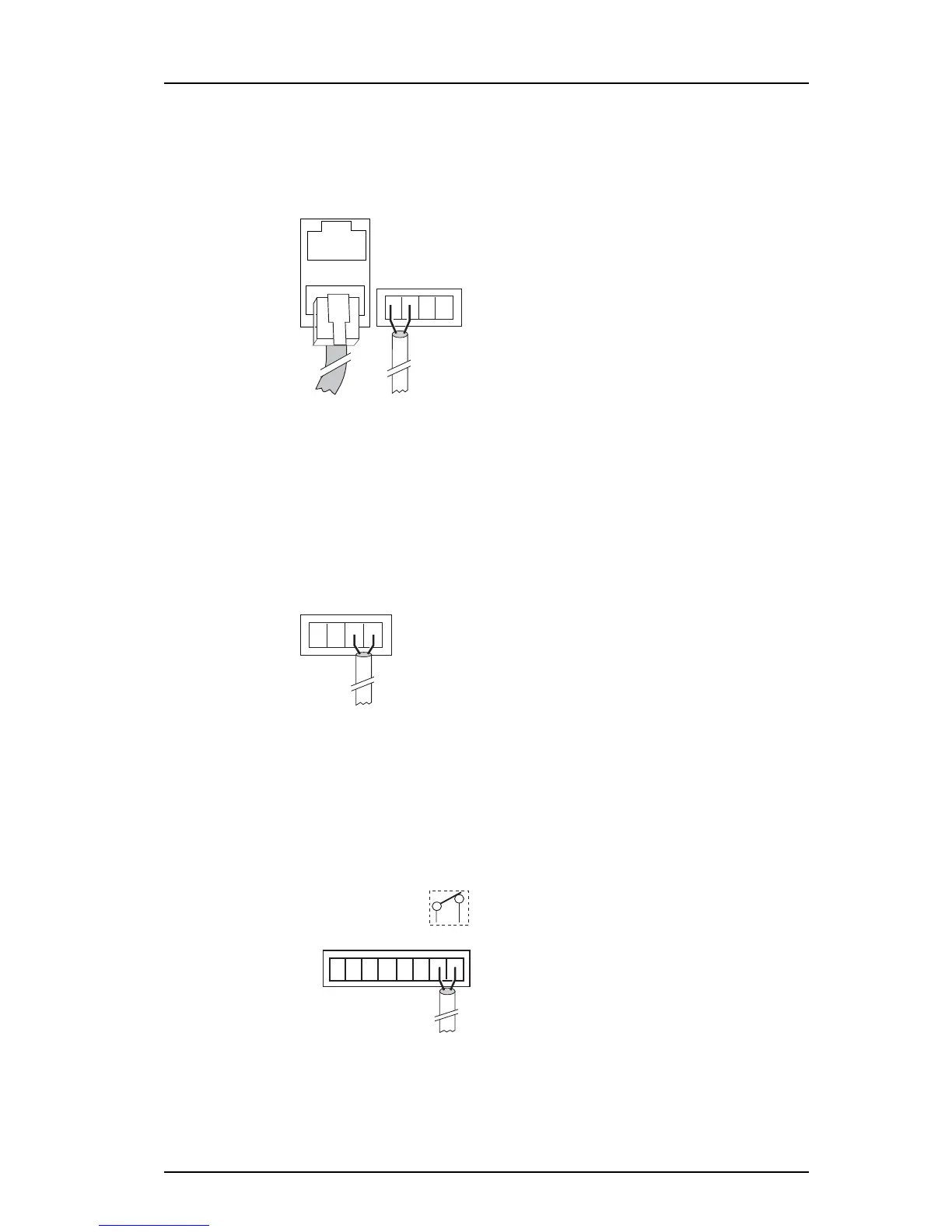
The module has two modular jacks (RJ45) marked S900 for connection of system 900 bus
cabling. If modular bus cabling is not used, connections are made with twisted pairs to 1
and 2 on screw connector A-bus.
Figure 12. Modular jacks for system bus and screw connectors for twisted pairs
4.4.4 LON Bus
Note: Requires the Elise3 LON variant.
The Elise3 module can be installed together with teleCare M modules. Connections are
made with twisted pairs to 1 and 2 on screw connector LON.
Figure 13. LON connector
4.4.5 Error Relay Output
A relay output is used to indicate Elise3 module malfunction and can also be used to
indicate other errors. See the application documentation for more information about
functionality. Connections are made with twisted pairs to 1 and 2 on screw connector
Error.
Figure 14. Error relay
When the Elise3 is running the relay is closed, i.e. the error relay output is activated when
the relay releases, for example if the power is dropped. At power up or restart the relay is
Figure 12.
Figure 13.
Figure 14.
S900
A-bus
1 2
LON
1 2
or
A-bus
1 2
LON
1 2
+V In In Out Out GND
Ext 1 2 1 2 Ext
Error
1 2
Error rela