TD 92679GB
12 April 2011 Ver. D
Installation Guide
Elise3
6
3 Description
The Elise3 front side has different status indications and is used for maintenance. The LEDs
indicates the status of the module and the management port makes it possible to have
direct connection to the module. It also has an SD card slot and two USB ports for external
temporary devices.
The rear side is used for connecting supply voltage, communication to Ascom systems,
external systems, inputs/outputs etc.
3.1 Overview of Connectors, Buttons and LEDs
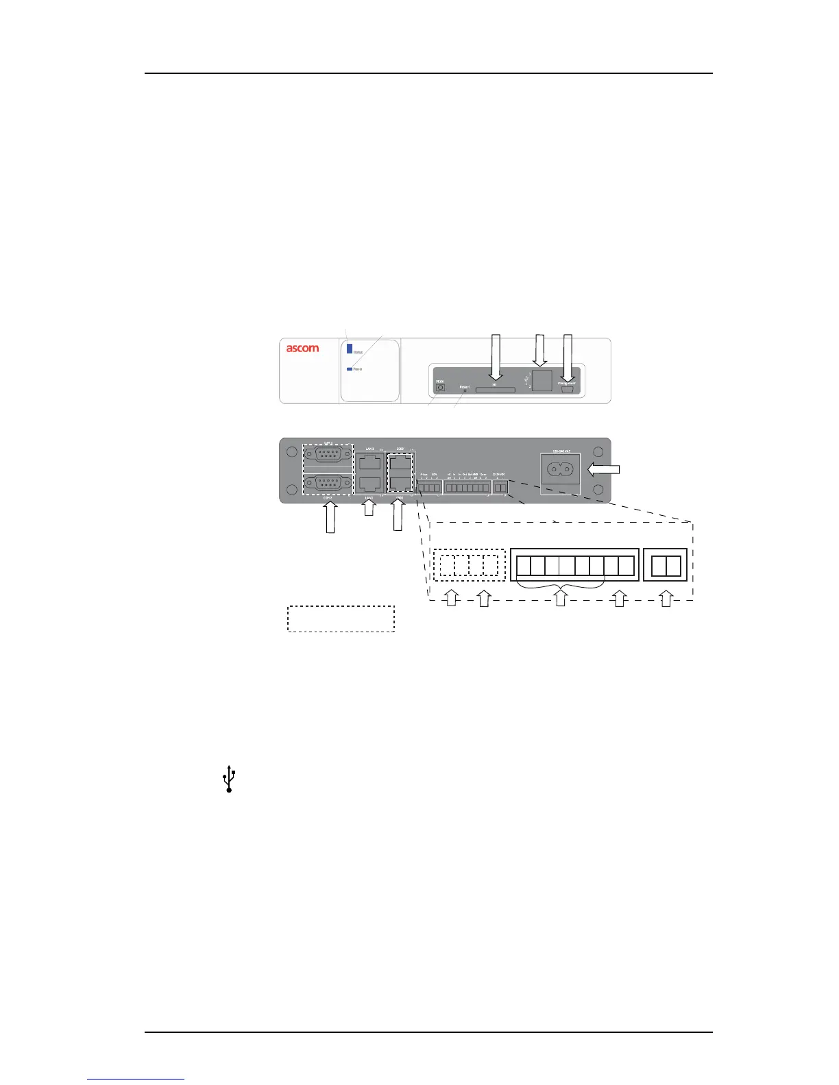
Figure 1. Connections, buttons and LEDs
Figure 1.
Front side
Status LED Indicates the module status, see 3.3 LED Indications
Power LED Indicates the power status, see 3.3 LED Indications
USB port 1
USB port 2
for upgrade of the Boot software on the field.
Management Mini-USB port for device management, see 4.5 Accessing Elise3 on
page 17.
Mode button The Mode button is a momentary push button with a blue LED. Used
for placing the module into specific modes by different push patterns.
Restart button The Restart button is a hole button that requires a paper clip (or similar)
to be able to push. Used for performing controlled restart and forced
restart, see
7.2 Restarting the Elise3 on page 30.
SD card slot Currently not used (for future releases)
Connection for
supply voltage
Power LED
Status LED
Front side
Rear side
External
power supply
Mode
button
Restart
button
Ethernet
ports
900-bus
COM ports
A-bus LON +V In In Out Out GND Error 12-24 V DC
1 2 1 2 Ext 1 2 1 2 Ext 1 2 + -
Management port
USB
ports
SD card slot
Error
relay
galvanically
isolated
inputs/outputs
A-bus LON-bus
Not applicable for the
Elise3 Lite version
1
2