VIPEDIA-12 Products – Installation Guide
U-0641-0344.docx – Issue: 8 complete, approved
Page 27 of 52
7.3.1.2 BOA01 - Auxiliary Microphone Interface Connections (Hardware Bypass Emergency
Microphone PPT and Speak Now and Listen-in)
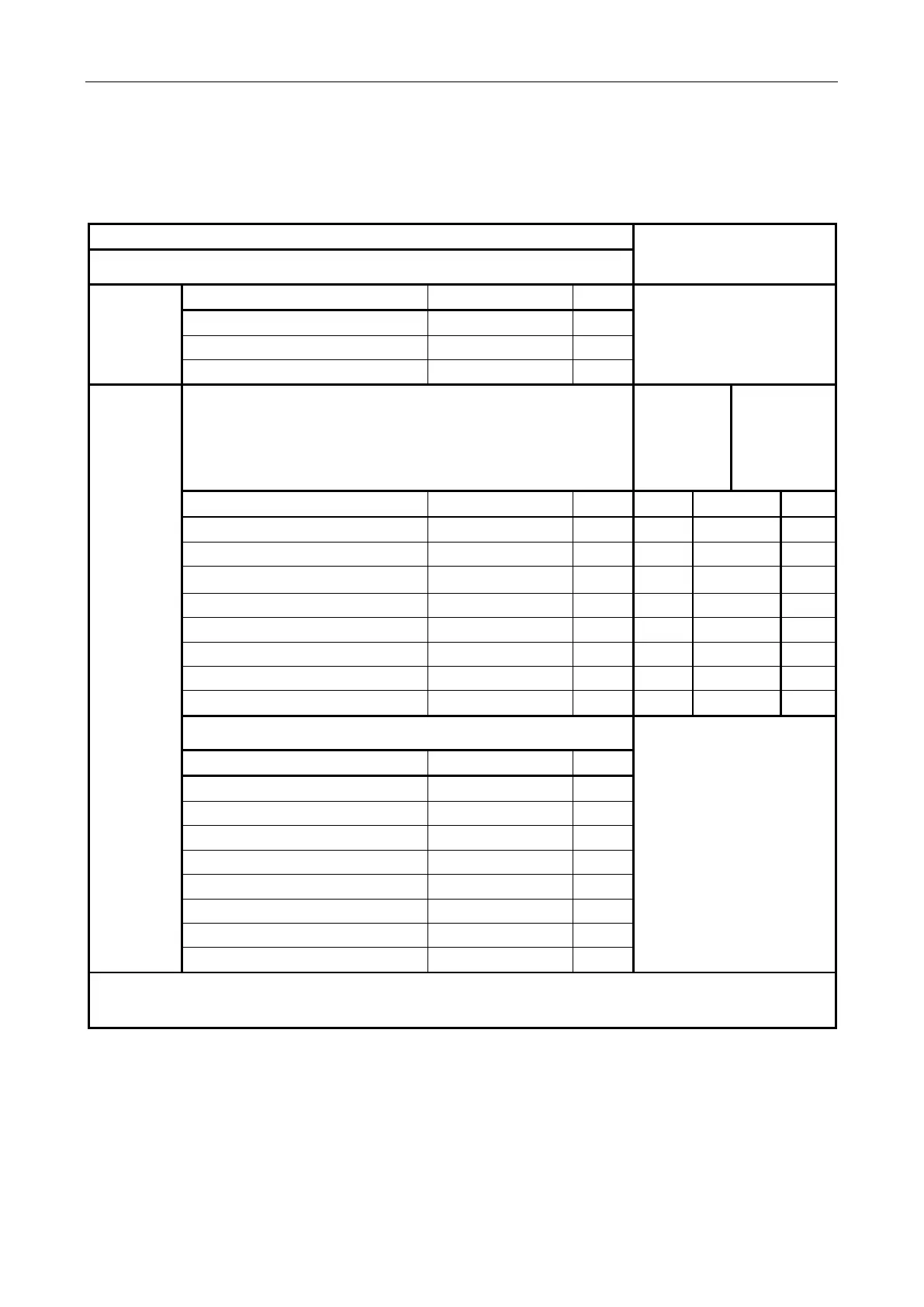
7.3.1.2.1 BOA01 - Auxiliary Microphone Interface 1 (MIC AUX 1)
Field Connection
Connection to VIPEDIA-12
(via CAT5 patch lead)
Screw Terminal
①
From
external
power supply
Description Signal Pin
Not applicable
(Connected to screw terminal
③
via the PCB.)
+V supply input (18 – 40 V) / 500 mA 24 V 1
+V supply input (18 – 40 V) / 500 mA 24 V 2
0 V supply 0 V 3
To/From
external
device
Screw Terminal
②
BOA01’s
RJ45
(see page 25)
④
VIPEDIA-12’s
RJ45
(see page 16)
⑭
(Top)
Description Signal Pin Pin T568B Pin
Fire microphone 2 PTT+ (Push-To-Talk) PTT2+ 1 1 WH/OR 1
Fire microphone 1 PTT+ (Push -To-Talk) PTT1+ 2 2 OR 2
Listen-in audio output 1+ LIST1+ 3 3 WH/GR 3
Listen-in audio output 1- LIST1- 4 6 GR 6
Fire Microphone 1 Speak Now LED S-NOW1 5 4 BL 4
Fire Microphone 2 Speak Now LED S-NOW2 6 5 WH/BL 5
Fire microphone 2 PTT- (Push -To-Talk) PTT2- 7 7 WH/BR 7
Fire microphone 1 PTT- (Push -To-Talk) PTT1- 8 8 BR 8
Screw Terminal
③
Not applicable
Description Signal Pin
Cable screen SCREEN 1
DC supply output (18 – 40 V) SUPPLY+ 2
Cable screen SCREEN 3
DC supply output (0 V) 0V 4
Cable screen SCREEN 5
DC supply output (18 – 40 V) SUPPLY+ 6
Cable screen SCREEN 7
DC supply output (0 V) 0V 8
An external DC power supply (18 – 40 V) must be connected to screw terminal ① if the external device
(microphone) is to be powered from the screw terminal block
③.