VIPEDIA-12 Products – Installation Guide
U-0641-0344.docx – Issue: 8 complete, approved
Page 30 of 52
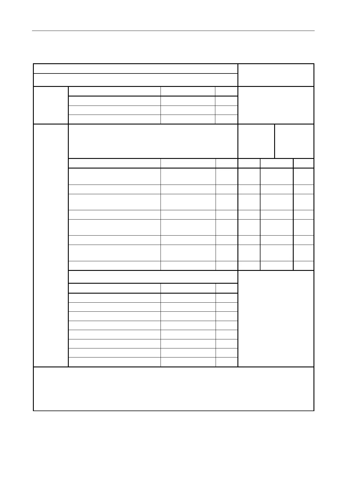
7.3.1.4 BOA01 - Contact Inputs (1 to 12) Connections
Field Connection
Connection to VIPEDIA-12
(via CAT5 patch lead)
Screw Terminal
①
From
external
power supply
Description Signal Pin
Not applicable
(Connected to screw terminal
③
via the PCB.)
+V supply input (18 – 40 V) / 500 mA 24 V 1
+V supply input (18 – 40 V) / 500 mA 24 V 2
0 V supply 0 V 3
To/From
external
device
Screw Terminal
②
BOA01’s
RJ45
(see page 25)
④
VIPEDIA-12’s
RJ45
(see page16)
⑩
Description Signal Pin Pin T568B Pin
Opto-coupled contact 1 [5, 9] (+ve) or
Analogue contact 1 [5, 9]
CI1+ [5, 9] 1 1 WH/OR 1
Opto-coupled contact 1 [5, 9] (-ve) CI1- [5, 9] 2 2 OR 2
Opto-coupled contact 2 [6, 10] (+ve) or
Analogue contact 2 [6, 10]
CI2+ [6, 10] 3 3 WH/GR 3
Opto-coupled contact 2 [6, 10] (-ve) CI2- [6, 10] 4 6 GR 6
Opto-coupled contact 3 [7, 11] (+ve) or
Analogue contact 3 [7, 11]
CI3+ [7, 11] 5 4 BL 4
Opto-coupled contact 3 [7, 11] (-ve) CI3- [7, 11] 6 5 WH/BL 5
Opto-coupled contact 4 [8, 12] (+ve) or
Analogue contact 4 [8, 12]
CI4+ [8, 12] 7 7 WH/BR 7
Opto-coupled contact 4 [8, 12] (-ve) CI4- [8, 12] 8 8 BR 8
Screw Terminal
③
Not applicable
Description Signal Pin
Cable screen SCREEN 1
DC supply output (18 – 40 V) SUPPLY+ 2
Cable screen SCREEN 3
DC supply output (0 V) 0V 4
Cable screen SCREEN 5
DC supply output (18 – 40 V) SUPPLY+ 6
Cable screen SCREEN 7
DC supply output (0 V) 0V 8
1) An external DC power supply (18 – 40 V) must be connected to screw terminal ① if the external device is to
be powered from the screw terminal block
③.
2) Contact: Numbers without brackets refer to CONTACTS IN 1-4 connector. Numbers within brackets refer to
CONTACTS IN 5-8 and 9-12 connector.
3) Contact is configurable as digital or analogue.
4) EOL resistors for digital contacts can be fitted to the BOA01 in manufacture as required.