VIPEDIA-12 Products – Installation Guide
U-0641-0344.docx – Issue: 8 complete, approved
Page 36 of 52
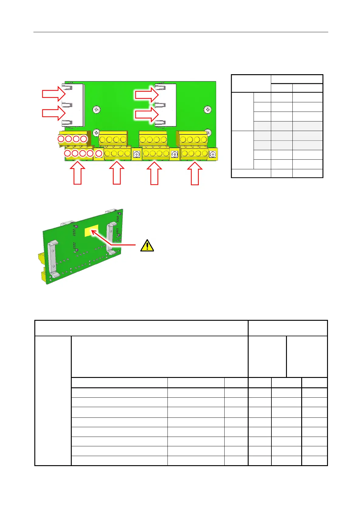
7.3.2 BOA02 Connections
7.3.2.1 BOA02 - Audio Input and Serial Interface (1 to 12) Connections
Field Connection
Connection to VIPEDIA-12
(via CAT5 patch lead)
To/From
external
device (e.g.
ASL
microphone)
Screw Terminal
BOA02’s
RJ45
(see page 36)
PORT 1 to 4
VIPEDIA-12’s
RJ45
(see page 16)
⑫
INPUTS 1 to 12
Description Signal Pin Pin T568B Pin
Balanced audio input+ AUDIO IN+ 1 1 WH/OR 1
Balanced audio input- AUDIO IN- 2 2 OR 2
RS485 data+ DXP 3 3 WH/GR 3
RS485 data- DXN 4 6 GR 6
DC supply output (18 – 40 V) +SUPPLY 5 4 BL 4
DC supply output (18 – 40 V) +SUPPLY 6 5 WH/BL 5
DC supply output (0 V) 0V 7 7 WH/BR 7
DC supply output (0 V) 0V 8 8 BR 8
For EMC compliance, ensure that 20 mm length of EMC gasket
1
(provided) is fixed to the gold-plated PCB land.
Ensure that its compression to 5 mm high (to DIN rail) does not
connect to other tracks on the PCB.
1
Wurth EMC gasket PN 3031010
Screw-in
Terminals
Pin T568-B
Rear 1 1
WH/OR
2 2
OR
3 3
WH/GR
4 6
GR
Front 5 4
BL
6 5
WH/BL
7 7
WH/BR
8 8
BR
9 (SCREEN) -