VIPEDIA-12 Products – Installation Guide
U-0641-0344.docx – Issue: 8 complete, approved
Page 32 of 52
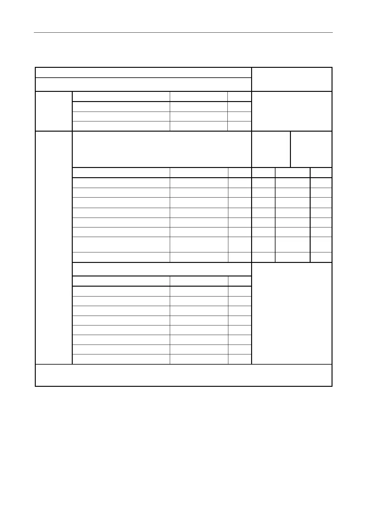
7.3.1.6 BOA01 - Fault/Voice Alarm/Control Relay and BMB01 Connections
Field Connection
Connection to VIPEDIA-12
(via CAT5 patch lead)
Screw Terminal
①
From
external
power supply
Description Signal Pin
Not applicable
(Connected to screw terminal
③
via the PCB.)
+V supply input (18 – 40 V) / 500 mA 24 V 1
+V supply input (18 – 40 V) / 500 mA 24 V 2
0 V supply 0 V 3
To/From
external
device
Screw Terminal
②
BOA01’s
RJ45
(see page 25)
④
VIPEDIA-12’s
RJ45
(see page16)
⑪
Description Signal Pin Pin T568B Pin
Fault relay N/C contact Relay 1 N/C 1 1 WH/OR 1
Fault relay COM contact Relay 1 COM 2 2 OR 2
Fault relay N/O contact Relay 1 N/O 3 3 WH/GR 3
Voice Alarm/Control relay N/C contact Relay 2 N/C 4 6 GR 6
Voice Alarm/Control relay COM contact Relay 2 COM 5 4 BL 4
Voice Alarm/Control relay N/O contact Relay 2 N/O 6 5 WH/BL 5
BMB control data / EIA RS485 9600
baud (Data+)
BMB DXP 7 7 WH/BR 7
As above but Data- BMB DXN 8 8 BR 8
Screw Terminal
③
Not applicable
Description Signal Pin
Cable screen SCREEN 1
DC supply output (18 – 40 V) SUPPLY+ 2
Cable screen SCREEN 3
DC supply output (0 V) 0V 4
Cable screen SCREEN 5
DC supply output (18 – 40 V) SUPPLY+ 6
Cable screen SCREEN 7
DC supply output (0 V) 0V 8
An external DC power supply (18 – 40 V) must be connected to screw terminal ① if the external device (BMB01) is
to be powered from the screw terminal block
③.