34
EN
Notices
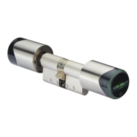
Explanation of terminology for the double cylinder
Term Description
I
Knob
(electronic side,
outside)
Knob on the electronic side consisting of:
· cylinder knob cover (
1 ),
· battery compartment (
12 ) for CR2 battery ( 3 ) and
· knob mount (
8 ).
II
Knob
(mechanical side,
inside)
Knob on the mechanical side consisting of:
· cylinder knob cover (
1 ),
· knob holder (
7 ) and
· knob mount (
8 ).
1
Knob cover The cylinder knob cover is a cover for the knob cylinder C100V3.
2
Special tool (optional) The knobs can be removed using special tool.
3
CR2 battery The CR2 battery supplies power to the electronic knob cylinder C100 V3.
4
Bolt washer The bolt washer is screwed into the respective side with the knob holder.
It has a flat area and a point-shaped marking that must point in the
direction of the cylinder housing on both sides.
5
Guide The guide on the locking disc guarantees that the knob is mounted
correctly.
6
Rectangular nut
The knob mount ( 8 ) is screwed into the knob holder ( 7 ) with the
rectangular nut and grub screw (
9 ).
7
Knob holder The knob holder supports the cylinder knob cover of the mechanical side
and is screwed into the knob mount.
8
Knob mount The knob on each side is inserted in the knob mount and screwed
together with the bolt washer (
4 ). In the process, there is only one way
to fit the parts together, which is determined by the position of the bolt
washer.
9
Grub screw
The knob mount ( 8 ) and the knob holder ( 7 ) are screwed together
with the grub screw and rectangular nut (
6 ).
10
Cylinder fixing screw The knob cylinder is fixed in the mortise lock by the cylinder fixing screw.
11
Cylinder housing
The cylinder housing is installed in the door with the cylinder fixing screw (10 ).
12
Battery
compartment
The battery compartment is screwed into the knob spindle with the knob
mount (
8 ). A CR2 3 V battery ( 3 ) must be inserted .
Approved 2017-08-16
 Loading...