Chapter 2: Hardware Setup
2-20
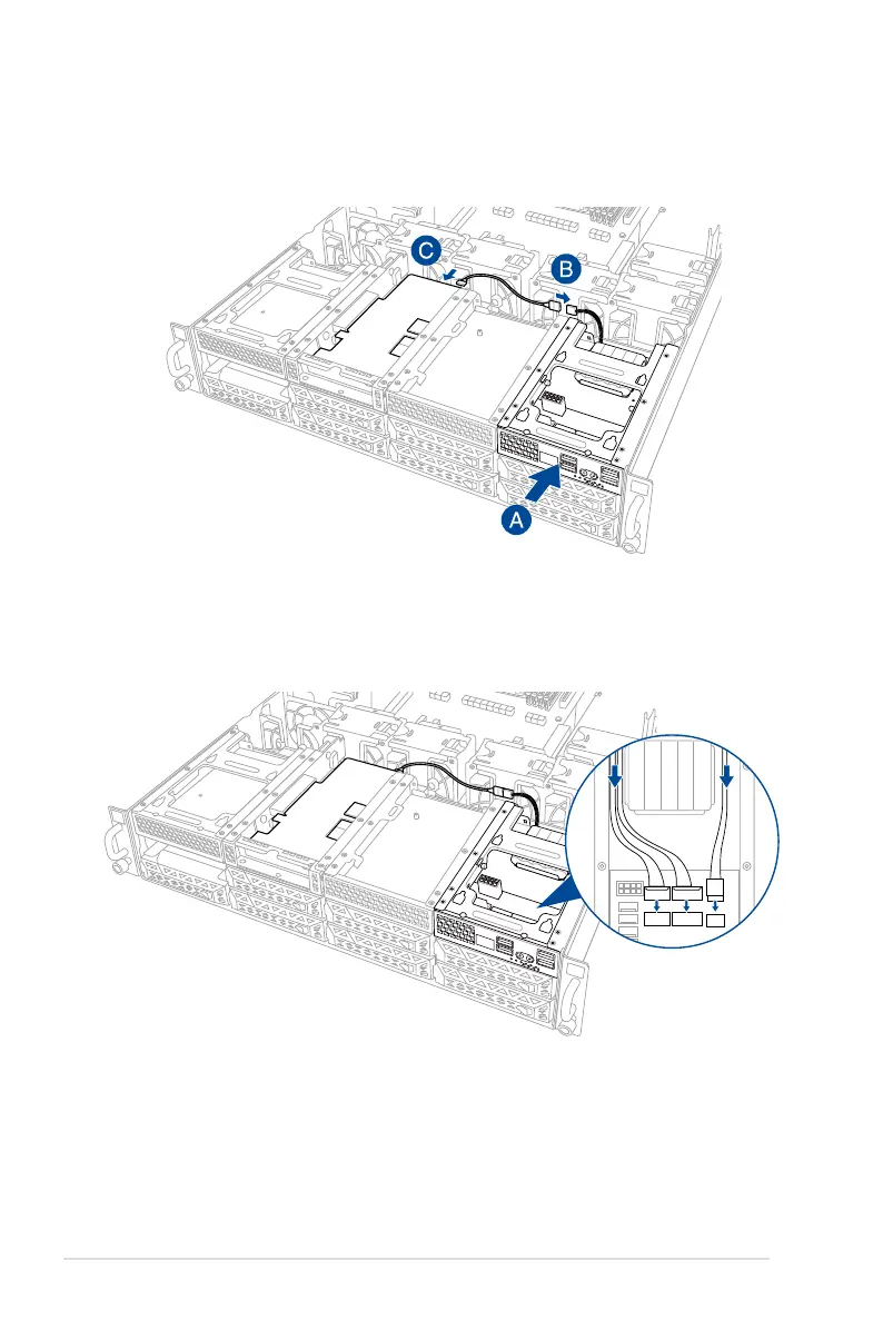
14. Insert the Cache Vault Power Module clip holder into the server system (A), then
connect the bundled extension cable to the cable from the Cache Vault Power Module
(B) and cable from the Cache Vault Flash Module (C).
15. Reconnect the three (3) cables to the Cache Vault Power Module clip holder, ensure
that the cables are not placed on top of the Cache Vault Power Module.
1
2
1
2