ASUS ESC4000A-E10
4-9
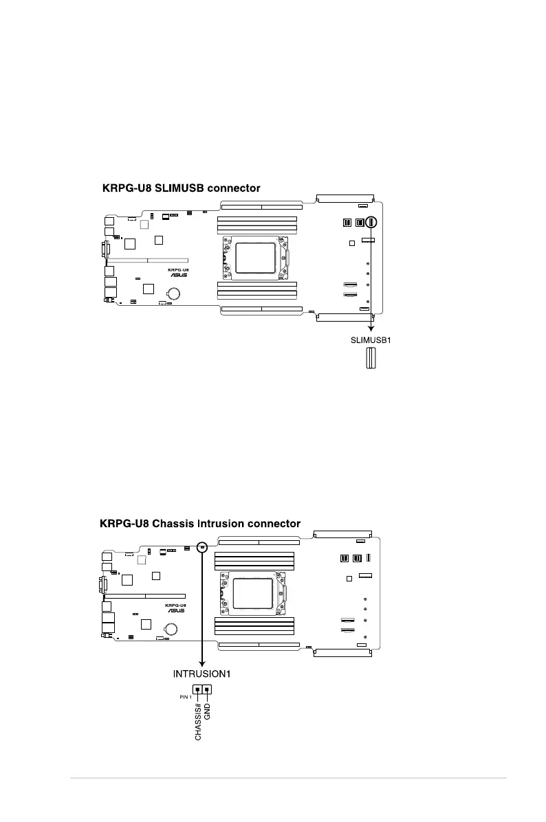
3. USB 3.2 Gen 1 connectors (SLIMUSB1)
Connect a compatible USB module cable to the SLIMUSB1 connector, and then install
the module to a slot opening at the back or front of the system chassis. You can enjoy
all the benets of USB 3.2 Gen 1 including faster data transfer speeds of up to 5 Gbps,
faster charging time for USB-chargeable devices, optimized power efciency, and
backward compatibility with USB 2.0. (SLIMUSB1 connector is used for the front USB
panel by default).
4. Chassis Intrusion (2-pin INTRUSION1)
These leads are for the intrusion detection feature for chassis with intrusion sensor or
microswitch. When you remove any chassis component, the sensor triggers and sends
a high level signal to these leads to record a chassis intrusion event. The default setting
is to short the CHASSIS# and the GND pin by a jumper cap to disable the function.