ASUS P5VDC-TVM SE 1-27
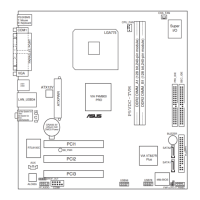
7. ATX power connectors (24-pin EATXPWR,
4-pin ATX12V)
These connectors are for an ATX power supply. The plugs from the power
supply are designed to t these connectors in only one orientation. Find the
proper orientation and push down rmly until the connectors completely t.
•
Do not forget to connect the 4-pin ATX +12 V power plug; otherwise, the
system will not boot up.
• When using an ATX 12 V PSU with 20-pin power plug, make sure that it
can provide 8 A on the +12 V lead and at least 1A on the +5V standby lead
(+5 VSB). The minimum recommended wattage is 300 W, or 350 W for a
fully congured system. The system may become unstable or may not boot
up if the power is inadequate.
• You must install a Power Supply Unit (PSU) with a higher power rating if
you intend to install additional devices.
 Loading...