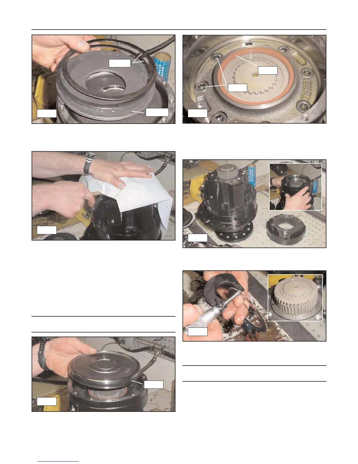
4. Remove the brake spring and shims. Make sure to
note the order of assembly to ensure correct
reassembly. (fig. 16-27)
5. Insert an air nozzle into the port closest to the rear
of the pump as shown. (fig. 16-28)
6. Cover the opening with a shop cloth and apply
moderate pressure to the top of the brake piston to
keep it in place when air is applied. (fig. 16-28)
7. Apply air to the port and the piston should slide
upwards so that it can be removed.
Note: There is a seal around the outer edge of the pis-
ton so it may pop loose rather than gently slide out.
8. Remove the piston from the motor. Inspect the
seal for any damage. (fig. 16-29)
9. Inspect the seal for any damage. (fig. 16-30)
10. Remove the allen bolts securing the upper casting
to the drive motor. (fig. 16-30)
11. Remove the upper casting from the drive motor to
expose the clutch discs. (fig. 16-31)
12. Inspect the discs for discoloration (blueing) or for
signs of excessive wear. (fig. 16-32)
Note: If any of the individual discs measure less than
.015” replace them as a set.
Assembly
1. Replace worn or damaged components, thorough-
ly clean all parts, then reassemble the motor by
reversing the disassembly procedure.
16-7
Rubber Track Loader
16. Hydraulic Component Service
16-27
16-28
Spring
Shims
16-29
Seal
16-30
Seal
Bolts
16-31
16-32


 To Next Page