Pillar Switch Panels (MP-1 & MP-2)
Removal (RT or LT panel)
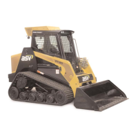
1. Remove the 3 screws/bolts securing the pillar
switch panel to the cab enclosure. (fig. 6-3)
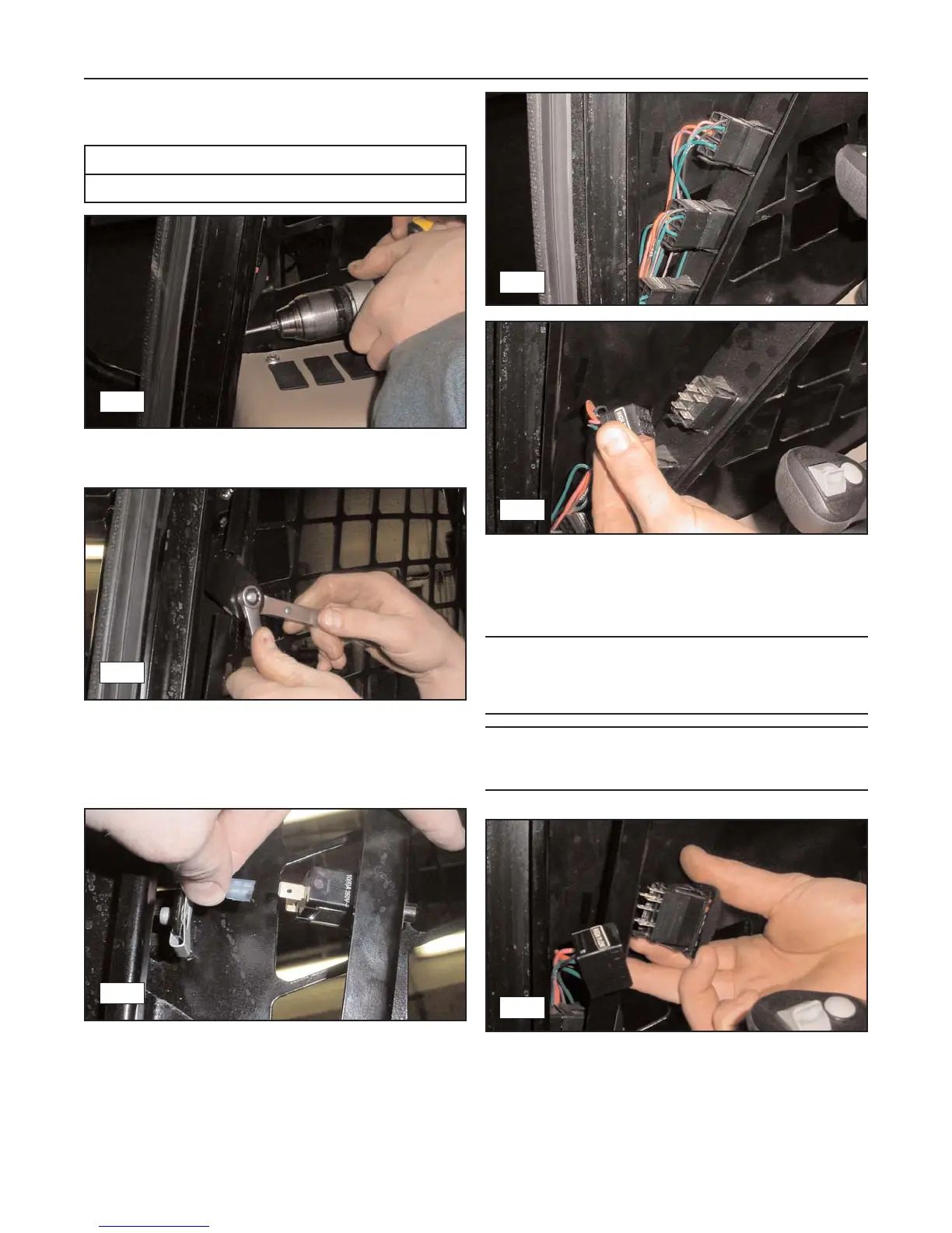
2. Remove the forward end of the gas spring from
the ball stud by following steps 1-2 in the Cab
Door Gas Spring removal procedure on page 6-1.
Then remove the ball stud. (fig. 6-4)
3. Once the ball stud has been removed, begin
removing the panel by pulling back on the top to
expose the wires connected to the dome light acti-
vation switch. Carefully disconnect them from the
switch. (fig. 6-5)
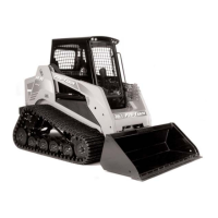
4. Pivot the panel further backward to expose the
connectors on the lower switches and disconnect
them. You may then remove the panel.
(fig. 6-6, 6-7)
Note: The connectors on the harness are labeled as
are the switches in the panel. Use these labels to
properly identify (match up) and reconnect the harness
to the switches during installation.
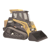
Note: At this point in the disassembly process, the
activation switches in the panel may be removed and
replaced if necessary. (fig. 6-8)
Installation (RT or LT panel)
1. To reinstall either panel, reverse the steps of the
removal procedure.
6-2
Rubber Track Loader
6. Operator Enclosure
6-3
6-4
6-6
6-7
6-5
6-8
Required Tools
Open or Box end Wrenches