Auxiliary Pump
Disassembly
1. With machine off and cool and with hydraulic actu-
ators relaxed, remove the drive pump from the
machine by following the procedure in section 11.
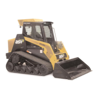
2. Remove the bolts securing the relief valve to the
housing. (fig. 16-64)
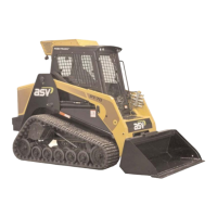
3. Inspect o-rings for proper shape and condition.
Replace if necessary. (fig. 16-65)
4. Remove the Allen bolts securing the cover onto the
pump. (fig. 16-66)
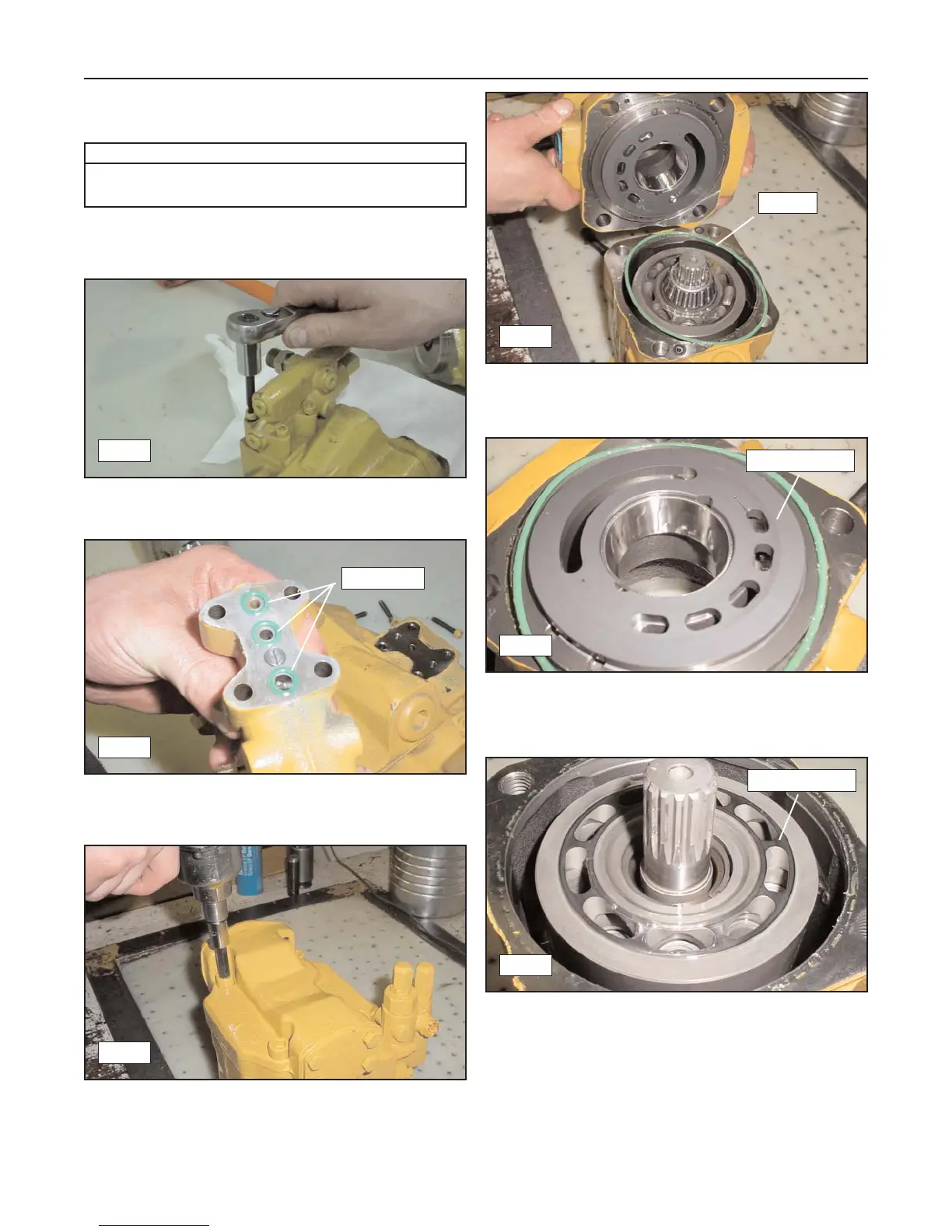
5. Lift the cover off to expose the pump components
and the o-ring seal. Inspect the o-ring for damage,
replace if necessary. (fig. 16-67)
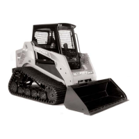
6. Inspect the valve plate face (both sides) for
scratches or any other damage that can be felt
with a fingernail. (fig. 16-68)
7. Inspect the barrel face for scratches or any other
damage that can be felt with a fingernail.
(fig. 16-69)
16-14
Rubber Track Loader
16. Hydraulic Component Service
Required Tools
Allen Wrench/Socket
Snap Ring Pliers
16-64
16-65
O-rings
16-66
16-67
16-68
16-69
O-ring
Inspect Face
Inspect Face