Chapter Overview
This chapter contains diagrams for the following PT-
70/80 circuits: hydraulic charge circuit, hydraulic auxil-
iary circuit, hydraulic drive circuit, loader valve,
hydraulic pilot generation (solenoid) block and electri-
cal attachment outlet. It also contains hose routing
information for the control configurations for the drive
and lift arm pilot controls.
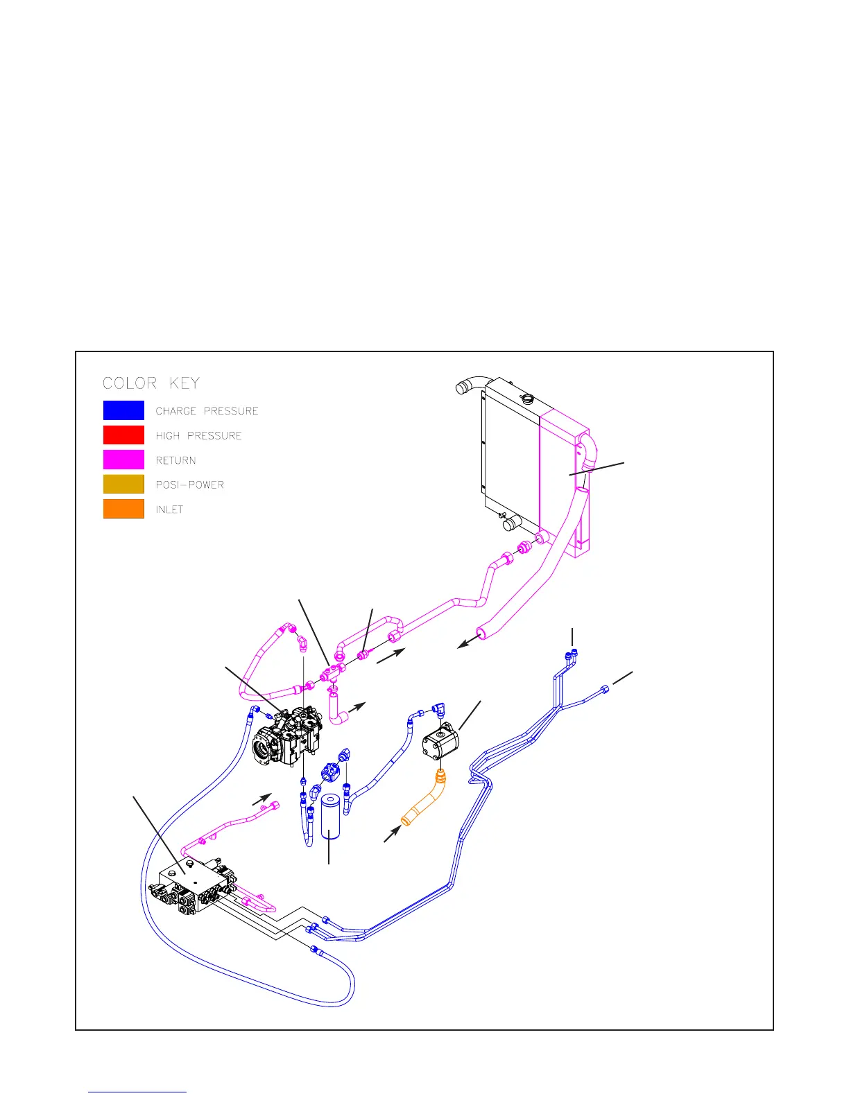
Figure 3-1 PT-70/80 Hydraulic Charge Circuit
Hydraulic Charge Circuit
3. Circuit Diagrams
3-1
OIL COOLER
TANK
INLET
CHARGE PUMP
FLOW
PILOT GEN BLOCK
CHARGE PRESSURE
TEST PORT
(475 +/- 30 PSI)
TO HYD Q/A (OPTIONAL PT-70)
TANK
5 MICRON FILTER
TANK
CHECK VALVE
(15 PSI)
CHECK VALVE
(0 PSI)
CHARGE PRESSURE
RELIEF VALVE
(475 +/- 30 PSI)